

Question: Question 4 Consider the steel framed floor beam system under a one way spanning concrete slab as shown in plan in Figure 2 . The
Question
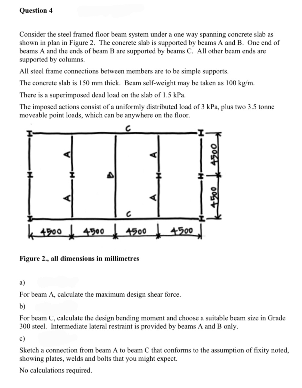
Consider the steel framed floor beam system under a one way spanning concrete slab as shown in plan in Figure The concrete slab is supported by beams A and B One end of beams A and the ends of beam B are supported by beams C All other beam ends are supported by columns.
All steel frame connections between members are to be simple supports.
The concrete slab is mm thick. Beam selfweight may be taken as
There is a superimposed dead load on the slab of kPa
The imposed actions consist of a uniformly distributed load of kPa plus two tonne moveable point loads, which can be anywhere on the floor.
Figure all dimensions in millimetres
a
For beam A calculate the maximum design shear force.
b
For beam C calculate the design bending moment and choose a suitable beam size in Grade steel. Intermediate lateral restraint is provided by beams A and B only.
c
Sketch a connection from beam A to beam C that conforms to the assumption of fixity noted, showing plates, welds and bolts that you might expect.
No calculations required.
Step by Step Solution
There are 3 Steps involved in it
1 Expert Approved Answer
Step: 1 Unlock

Question Has Been Solved by an Expert!
Get step-by-step solutions from verified subject matter experts
Step: 2 Unlock
Step: 3 Unlock