

Question: Question 4 Figure Q4 below shows a splice connection between two identical beams of UB533x210x109 in S355 steel. The splice connection is designed to take
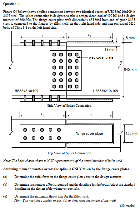
Question 4 Figure Q4 below shows a splice connection between two identical beams of UB533x210x109 in S355 steel. The splice connection is designed to take a design shear load of 400 EN and a design moment of 6001Nm. The flange cover plate with dimensions of 160x15mm and of grade S355 steel is connected to the flanges by fillet weld on the right-hand side and non-preloaded M20 bolts of Class 8.8 on the left-hand side. LI L 15 mm 19 mm web cover plate 540 mm UB533x210x109 UB533x210x109 Side View of Splice Connection Li Li OO 0 0 flange cover plate 160 mm O Top View of Splice Connection Note: The bolts shown above is NOT representative of the actual number of bolts used. Assuming moment transfer across the splice is ONLY taken by the flange cover plates. (a) Determine the axial force in the flange cover plates due to the design moment. (6) Determine the number of bolts required and the detailing for the bolts. Adopt the standard detailing in the design table whenever possible. (c) Determine the minimum throat size for the fillet weld. Hint: You need the solution in part (b) to determine the length of the weld. (20 marks) Question 4 Figure Q4 below shows a splice connection between two identical beams of UB533x210x109 in S355 steel. The splice connection is designed to take a design shear load of 400 EN and a design moment of 6001Nm. The flange cover plate with dimensions of 160x15mm and of grade S355 steel is connected to the flanges by fillet weld on the right-hand side and non-preloaded M20 bolts of Class 8.8 on the left-hand side. LI L 15 mm 19 mm web cover plate 540 mm UB533x210x109 UB533x210x109 Side View of Splice Connection Li Li OO 0 0 flange cover plate 160 mm O Top View of Splice Connection Note: The bolts shown above is NOT representative of the actual number of bolts used. Assuming moment transfer across the splice is ONLY taken by the flange cover plates. (a) Determine the axial force in the flange cover plates due to the design moment. (6) Determine the number of bolts required and the detailing for the bolts. Adopt the standard detailing in the design table whenever possible. (c) Determine the minimum throat size for the fillet weld. Hint: You need the solution in part (b) to determine the length of the weld. (20 marks)
Step by Step Solution
There are 3 Steps involved in it

Get step-by-step solutions from verified subject matter experts