

Question: 1. Build the circuit shown in Fig. 1-2 below using a BZX85C4V7 Zener diode (For Diode simulations in QUCS use 1N4732 to replace BZX85C
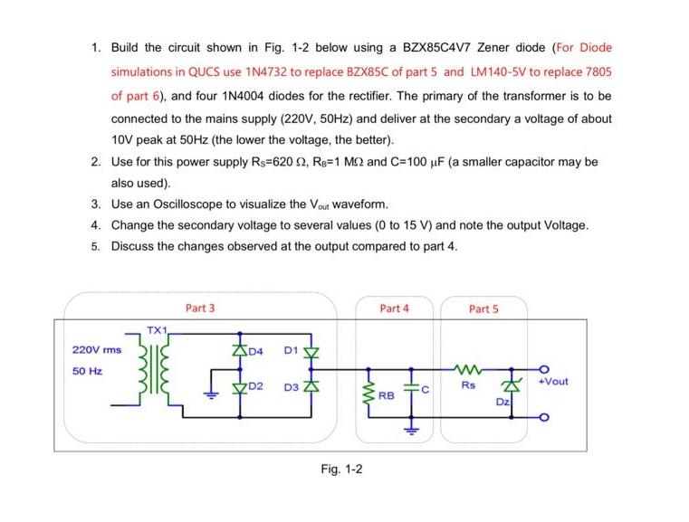
1. Build the circuit shown in Fig. 1-2 below using a BZX85C4V7 Zener diode (For Diode simulations in QUCS use 1N4732 to replace BZX85C of part 5 and LM140-5V to replace 7805 of part 6), and four 1N4004 diodes for the rectifier. The primary of the transformer is to be connected to the mains supply (220V, 50Hz) and deliver at the secondary a voltage of about 10V peak at 50Hz (the lower the voltage, the better). 2. Use for this power supply Rs=620 52, Re=1 MC2 and C=100 F (a smaller capacitor may be also used). 3. Use an Oscilloscope to visualize the Vout waveform. 4. Change the secondary voltage to several values (0 to 15 V) and note the output Voltage. 5. Discuss the changes observed at the output compared to part 4. 220V rms 50 Hz TX1 Part 3 ZD4 D2 D1 D3 www Fig. 1-2 Part 4 RB H H Part 5 Rs Dz +Vout
Step by Step Solution
3.53 Rating (160 Votes )
There are 3 Steps involved in it

Get step-by-step solutions from verified subject matter experts