

Question: Question 5 (a) Draw a block diagram for a Smith predictor control system including both the set-point and disturbance, and explain why the Smith predictor
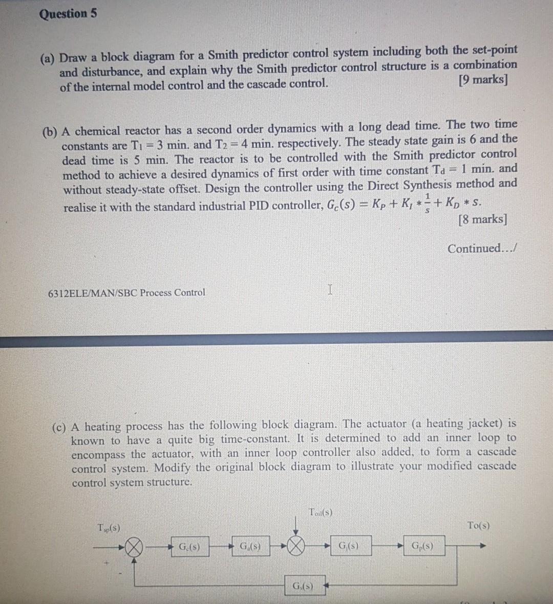
Question 5 (a) Draw a block diagram for a Smith predictor control system including both the set-point and disturbance, and explain why the Smith predictor control structure is a combination of the internal model control and the cascade control. [9 marks] (b) A chemical reactor has a second order dynamics with a long dead time. The two time constants are T1 = 3 min. and T2 = 4 min. respectively. The steady state gain is 6 and the dead time is 5 min. The reactor is to be controlled with the Smith predictor control method to achieve a desired dynamics of first order with time constant Ta = 1 min. and without steady-state offset. Design the controller using the Direct Synthesis method and realise it with the standard industrial PID controller, G. (s) = Kp + K, ** + Ky [8 marks] *S. Continued.../ 6312ELE/MAN/SBC Process Control (c) A heating process has the following block diagram. The actuator (a heating jacket) is known to have a quite big time-constant. It is determined to add an inner loop to encompass the actuator, with an inner loop controller also added, to form a cascade control system. Modify the original block diagram to illustrate your modified cascade control system structure. To(s Tsp(s) To(s) G () G(S) G(S) Gp(s) G(s) Question 5 (a) Draw a block diagram for a Smith predictor control system including both the set-point and disturbance, and explain why the Smith predictor control structure is a combination of the internal model control and the cascade control. [9 marks] (b) A chemical reactor has a second order dynamics with a long dead time. The two time constants are T1 = 3 min. and T2 = 4 min. respectively. The steady state gain is 6 and the dead time is 5 min. The reactor is to be controlled with the Smith predictor control method to achieve a desired dynamics of first order with time constant Ta = 1 min. and without steady-state offset. Design the controller using the Direct Synthesis method and realise it with the standard industrial PID controller, G. (s) = Kp + K, ** + Ky [8 marks] *S. Continued.../ 6312ELE/MAN/SBC Process Control (c) A heating process has the following block diagram. The actuator (a heating jacket) is known to have a quite big time-constant. It is determined to add an inner loop to encompass the actuator, with an inner loop controller also added, to form a cascade control system. Modify the original block diagram to illustrate your modified cascade control system structure. To(s Tsp(s) To(s) G () G(S) G(S) Gp(s) G(s)
Step by Step Solution
There are 3 Steps involved in it

Get step-by-step solutions from verified subject matter experts