

Question: Question 6 . Consider the Common Emitter ( CE ) amplifier in figure B 3 below. The capacitor C i n = 1 F ,
Question
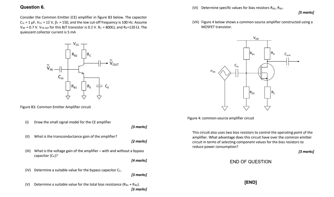
Consider the Common Emitter CE amplifier in figure B below. The capacitor and the low cutoff frequency is Hz Assume for this BJT transistor is and The quiescent collector current is mA
Figure B: Common Emitter Amplifier circuit
I Draw the small signal model for the CE amplifier
marks
II What is the transconductance gain of the amplifier?
marks
III What is the voltage gain of the amplifier with and without a bypass capacitor
marks
IV Determine a suitable value for the bypass capacitor
marks
V Determine a suitable value for the total bias resistance :
Step by Step Solution
There are 3 Steps involved in it
1 Expert Approved Answer
Step: 1 Unlock

Question Has Been Solved by an Expert!
Get step-by-step solutions from verified subject matter experts
Step: 2 Unlock
Step: 3 Unlock