

Question: Question B-1. The geared system shown in Figure QB-1 is used to transfer the power generated by an electric motor connected to shaft carrying
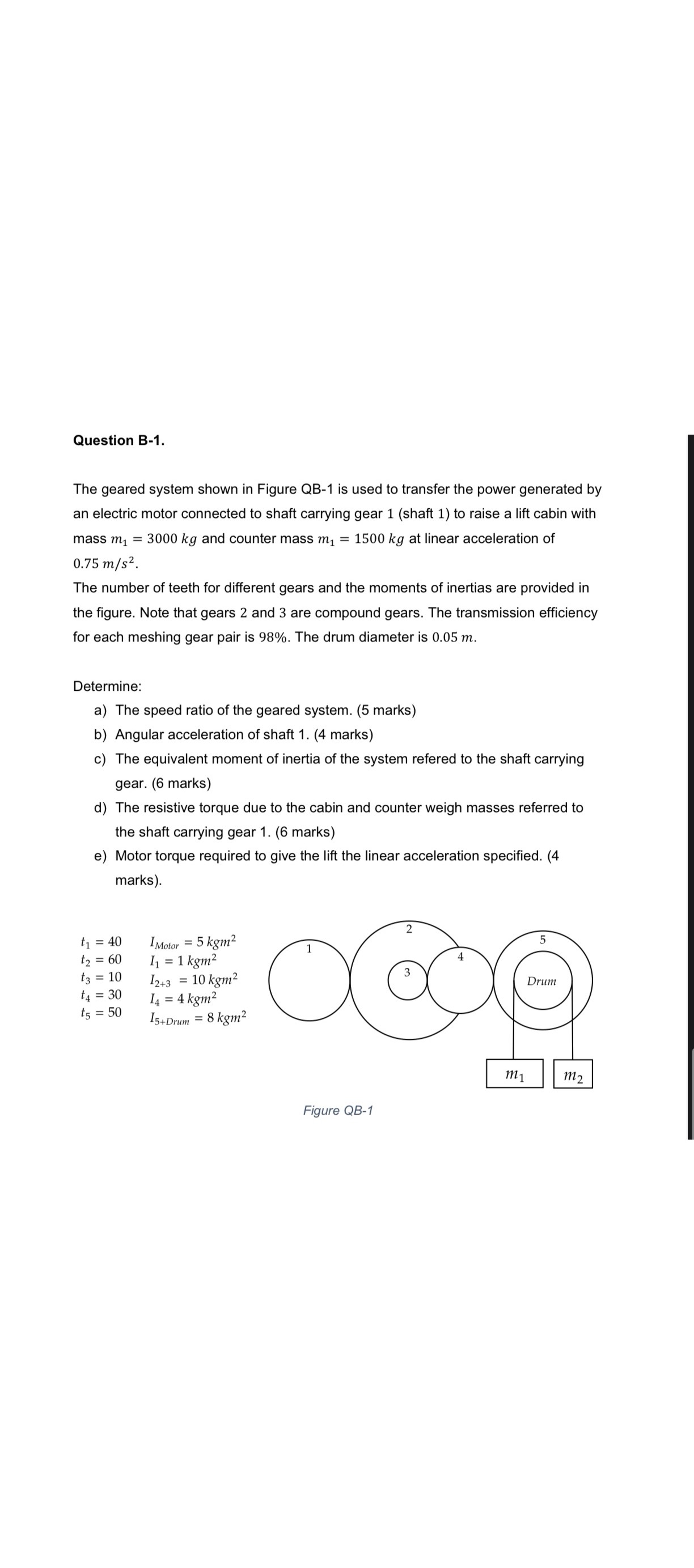
Question B-1. The geared system shown in Figure QB-1 is used to transfer the power generated by an electric motor connected to shaft carrying gear 1 (shaft 1) to raise a lift cabin with mass m = 3000 kg and counter mass m = 1500 kg at linear acceleration of 0.75 m/s. The number of teeth for different gears and the moments of inertias are provided in the figure. Note that gears 2 and 3 are compound gears. The transmission efficiency for each meshing gear pair is 98%. The drum diameter is 0.05 m. Determine: a) The speed ratio of the geared system. (5 marks) b) Angular acceleration of shaft 1. (4 marks) c) The equivalent moment of inertia of the system refered to the shaft carrying gear. (6 marks) d) The resistive torque due to the cabin and counter weigh masses referred to the shaft carrying gear 1. (6 marks) e) Motor torque required to give the lift the linear acceleration specified. (4 marks). IMotor = 5 kgm t = 40 t2 = 60 11 = 1 kgm t3 = 10 12+3 = 10 kgm t = 30 14 = 4 kgm t5 = 50 15+Drum = 8 kgm 2 5 4 Drum m1 m2 Figure QB-1
Step by Step Solution
There are 3 Steps involved in it

Get step-by-step solutions from verified subject matter experts