Question: Write a technical description for the Brita Stainless Steel Water Bottle with Filter, 20 Ounce Premium Double Insulated Water Bottle, BPA Free, Carbon. This description
Write a technical description for the Brita Stainless Steel Water Bottle with Filter, 20 Ounce Premium Double Insulated Water Bottle, BPA Free, Carbon. This description should include the following sections:
Introduction:
Clearly identify the Brita water bottle by its full name, emphasizing its key features such as the stainless steel material, double insulation, and the carbon filter.
Provide a general overview of its size (20 ounces), shape, and primary function (to filter and carry drinking water).
Mention any relevant background information about the Brita brand's foray into portable water filtration solutions and any notable innovations with this model.
Description and Function of Major Parts:
First Major Part: Filter
Define the filter, mentioning it is a carbon-based component designed for portable use.
Detail its dimensions, material (carbon filter), and any unique design elements that make it suitable for a water bottle.
Describe the function of the filter, such as reducing chlorine taste and odor from tap water, making water taste better on-the-go.
Explain how the filter fits within the water bottle and its relationship with the water bottle's body and cap.
Mention the filter's lifespan or capacity (e.g., equivalent to filtering a certain number of plastic water bottles) and how it is replaced.
Second Major Part: Stainless Steel Body
Describe the body's double-insulated stainless steel construction, emphasizing its durability and ability to keep water cold for hours.
Note the shape, dimensions, and any special design features like the finish or color options.
Explain how the body is designed for portability and convenience (e.g., fits in most car cup holders, has a leak-proof cap).
Third Major Part: Cap
Discuss the design and function of the cap, including how it contributes to the bottle's leak-proof quality and ease of drinking.
If applicable, describe any additional features of the cap, such as a built-in carrying loop.
Summary Description:
Summarize how the Brita Stainless Steel Water Bottle with Filter functions as a whole when assembled and in use. Highlight how water is drawn through the filter into the mouthpiece, the benefits of the double insulation, and the overall convenience and environmental benefits of using this bottle for daily hydration needs.
Ensure to include at least one image of the Brita Stainless Steel Water Bottle with Filter, 20 Ounce Premium Double Insulated Water Bottle, BPA Free, Carbon, citing the source of the image if it is found online. The aim is to provide a comprehensive and detailed technical description that emphasizes the unique features and benefits of this specific Brita water bottle model.
This one of the the examples:
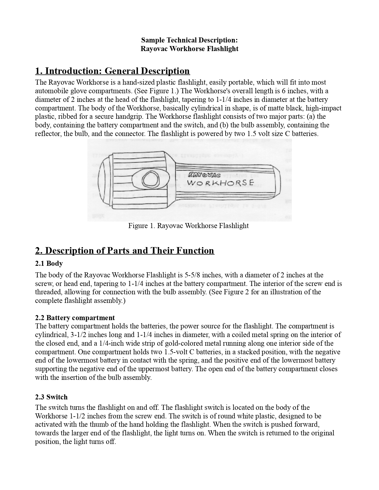
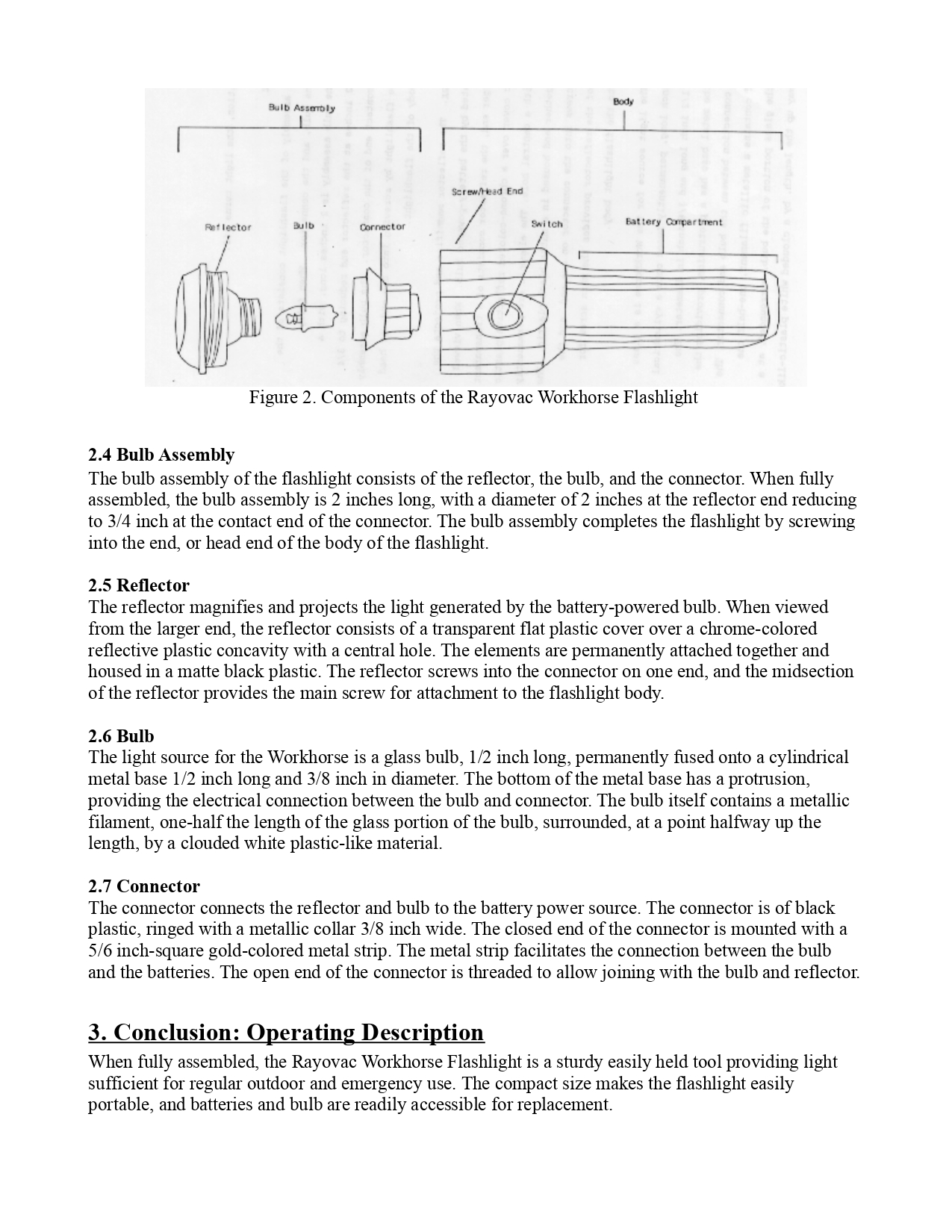
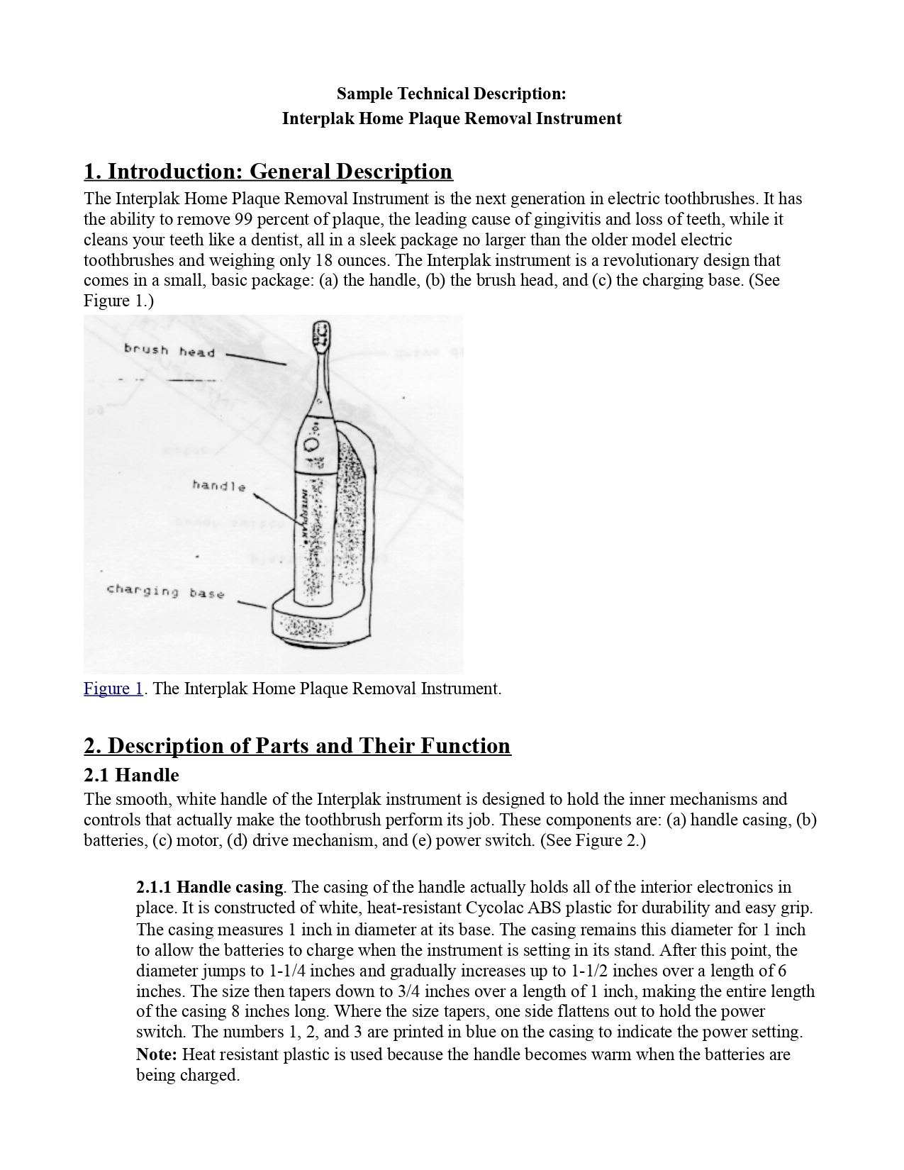
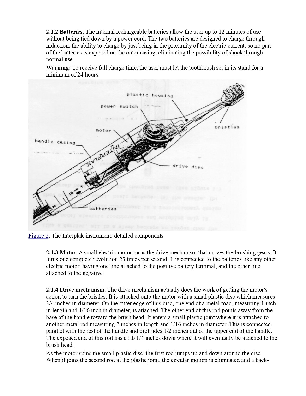
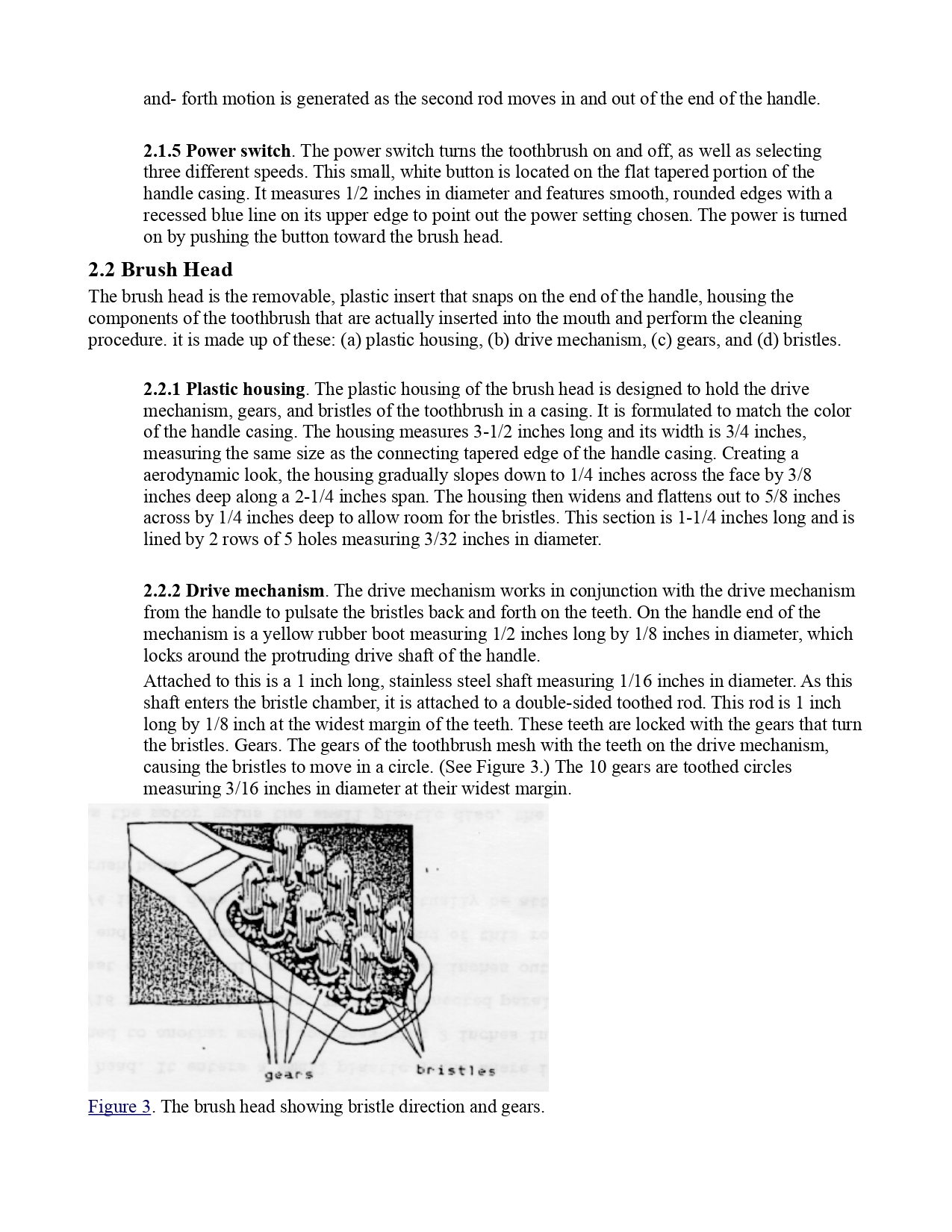
Sample Technical Description: Rayovac Workhorse Flashlight 1. Introduction: General Description The Rayovac Workhorse is a hand-sized plastic flashlight, easily portable, which will fit into most automobile glove compartments. (See Figure 1.) The Workhorse's overall length is 6 inches, with a diameter of 2 inches at the head of the flashlight, tapering to 1-1/4 inches in diameter at the battery compartment. The body of the Workhorse, basically cylindrical in shape, is of matte black, high-impact plastic, ribbed for a secure handgrip. The Workhorse flashlight consists of two major parts: (a) the body, containing the battery compartment and the switch, and (b) the bulb assembly, containing the reflector, the bulb, and the connector. The flashlight is powered by two 1.5 volt size C batteries. 'm@'&'@ wo RRHORS E '. Figure 1. Rayovac Workhorse Flashlight 2. Description of Parts and Their Function 2.1 Body The body of the Rayovac Workhorse Flashlight is 5-5/8 inches, with a diameter of 2 inches at the screw, or head end, tapering to 1-1/4 inches at the battery compartment. The interior of the screw end is threaded, allowing for connection with the bulb assembly. (See Figure 2 for an illustration of the complete flashlight assembly.) 2.2 Battery compartment The battery compartment holds the batteries, the power source for the flashlight. The compartment is cylindrical, 3-1/2 inches long and 1-1/4 inches in diameter, with a coiled metal spring on the interior of the closed end, and a 1/4-inch wide strip of gold-colored metal running along one interior side of the compartment. One compartment holds two 1.5-volt C batteries, in a stacked position, with the negative end of the lowermost battery in contact with the spring, and the positive end of the lowermost battery supporting the negative end of the uppermost battery. The open end of the battery compartment closes with the insertion of the bulb assembly. 2.3 Switch The switch turns the flashlight on and off. The flashlight switch is located on the body of the Workhorse 1-1/2 inches from the screw end. The switch is of round white plastic, designed to be activated with the thumb of the hand holding the flashlight. When the switch 1s pushed forward, towards the larger end of the flashlight, the light tumns on. When the switch is returned to the original position, the light turns off. Bulb Assembly Body Screw/Head End Reflector Bult Cornector Switch Battery Compartment Figure 2. Components of the Rayovac Workhorse Flashlight 2.4 Bulb Assembly The bulb assembly of the flashlight consists of the reflector, the bulb, and the connector. When fully assembled, the bulb assembly is 2 inches long, with a diameter of 2 inches at the reflector end reducing to 3/4 inch at the contact end of the connector. The bulb assembly completes the flashlight by screwing into the end, or head end of the body of the flashlight. 2.5 Reflector The reflector magnifies and projects the light generated by the battery-powered bulb. When viewed from the larger end, the reflector consists of a transparent flat plastic cover over a chrome-colored reflective plastic concavity with a central hole. The elements are permanently attached together and housed in a matte black plastic. The reflector screws into the connector on one end, and the midsection of the reflector provides the main screw for attachment to the flashlight body. 2.6 Bulb The light source for the Workhorse is a glass bulb, 1/2 inch long, permanently fused onto a cylindrical metal base 1/2 inch long and 3/8 inch in diameter. The bottom of the metal base has a protrusion, providing the electrical connection between the bulb and connector. The bulb itself contains a metallic filament, one-half the length of the glass portion of the bulb, surrounded, at a point halfway up the length, by a clouded white plastic-like material. 2.7 Connector The connector connects the reflector and bulb to the battery power source. The connector is of black plastic, ringed with a metallic collar 3/8 inch wide. The closed end of the connector is mounted with a 5/6 inch-square gold-colored metal strip. The metal strip facilitates the connection between the bulb and the batteries. The open end of the connector is threaded to allow joining with the bulb and reflector. 3. Conclusion: Operating Description When fully assembled, the Rayovac Workhorse Flashlight is a sturdy easily held tool providing light sufficient for regular outdoor and emergency use. The compact size makes the flashlight easily portable, and batteries and bulb are readily accessible for replacement.Sample Technical Description: Interplak Home Plaque Removal Instrument 1. Introduction: General Description The Interplak Home Plaque Removal Instrument is the next generation in electric toothbrushes. It has the ability to remove 99 percent of plaque, the leading cause of gingivitis and loss of teeth, while it cleans your teeth like a dentist, all in a sleek package no larger than the older model electric toothbrushes and weighing only 18 ounces. The Interplak instrument is a revolutionary design that comes in a small, basic package: (a) the handle, (b) the brush head, and (c) the charging base. (See Figure 1.) brush head handle ':h-.l'q'_r,J base Figure 1. The Interplak Home Plaque Removal Instrument. 2. Description of Parts and Their Function 2.1 Handle The smooth, white handle of the Interplak instrument is designed to hold the inner mechanisms and controls that actually make the toothbrush perform its job. These components are: (a) handle casing, (b) batteries, () motor, (d) drive mechanism, and (e) power switch. (See Figure 2.) 2.1.1 Handle casing. The casing of the handle actually holds all of the nterior electronics in place. It is constructed of white, heat-resistant Cycolac ABS plastic for durability and easy grip. The casing measures 1 inch in diameter at its base. The casing remains this diameter for 1 inch to allow the batteries to charge when the instrument is setting in its stand. After this point, the diameter jumps to 1-1/4 inches and gradually increases up to 1-1/2 inches over a length of 6 inches. The size then tapers down to 3/4 inches over a length of 1 inch, making the entire length of the casing 8 inches long. Where the size tapers, one side flattens out to hold the power switch. The numbers 1, 2, and 3 are printed in blue on the casing to indicate the power setting. Note: Heat resistant plastic is used because the handle becomes warm when the batteries are being charged. 2.1.2 Batteries. The internal rechargeable batteries allow the user up to 12 minutes of use without being tied down by a power cord. The two batteries are designed to charge through induction, the ability to charge by just being in the proximity of the electric current, so no part of the batteries is exposed on the outer casing, eliminating the possibility of shock through normal use. Warning: To receive full charge time, the user must let the toothbrush set in its stand for a minimum of 24 hours. o a" plastic housing ! W '} power switch f',#i;// bristles motop handl e casing drive disc batteries Figure 2. The Interplak instrument: detailed components 2.1.3 Motor. A small electric motor turns the drive mechanism that moves the brushing gears. It turns one complete revolution 23 times per second. It is connected to the batteries like any other electric motor, having one line attached to the positive battery terminal, and the other line attached to the negative. 2.1.4 Drive mechanism. The drive mechanism actually does the work of getting the motor's action to turn the bristles. It is attached onto the motor with a small plastic disc which measures 3/4 inches in diameter. On the outer edge of this disc, one end of a metal road, measuring 1 inch m length and 1/16 inch m diameter, 1s attached. The other end of this rod points away from the base of the handle toward the brush head. It enters a small plastic joint where it is attached to another metal rod measuring 2 inches in length and 1/16 inches in diameter. This is connected parallel with the rest of the handle and protrudes 1/2 inches out of the upper end of the handle. The exposed end of this rod has a rib 1/4 mches down where it will eventually be attached to the brush head. As the motor spins the small plastic disc, the first rod jumps up and down around the disc. When it joins the second rod at the plastic joint, the circular motion is eliminated and a back- and- forth motion is generated as the second rod moves in and out of the end of the handle. 2.1.5 Power switch. The power switch turns the toothbrush on and off, as well as selecting three different speeds. This small, white button is located on the flat tapered portion of the handle casing. It measures 1/2 inches in diameter and features smooth, rounded edges with a recessed blue line on its upper edge to point out the power setting chosen. The power is turned on by pushing the button toward the brush head. 2.2 Brush Head The brush head is the removable, plastic insert that snaps on the end of the handle, housing the components of the toothbrush that are actually inserted into the mouth and perform the cleaning procedure. it is made up of these: (a) plastic housing, (b) drive mechanism, (c) gears, and (d) bristles. 2.2.1 Plastic housing. The plastic housing of the brush head is designed to hold the drive mechanism, gears, and bristles of the toothbrush in a casing. It is formulated to match the color of the handle casing. The housing measures 3-1/2 inches long and its width is 3/4 inches, measuring the same size as the connecting tapered edge of the handle casing. Creating a aerodynamic look, the housing gradually slopes down to 1/4 inches across the face by 3/8 inches deep along a 2-1/4 inches span. The housing then widens and flattens out to 5/8 inches across by 1/4 inches deep to allow room for the bristles. This section is 1-1/4 inches long and is lined by 2 rows of 5 holes measuring 3/32 inches in diameter. 2.2.2 Drive mechanism. The drive mechanism works in conjunction with the drive mechanism from the handle to pulsate the bristles back and forth on the teeth. On the handle end of the mechanism is a yellow rubber boot measuring 1/2 inches long by 1/8 inches in diameter, which locks around the protruding drive shaft of the handle. Attached to this is a 1 inch long, stainless steel shaft measuring 1/16 inches in diameter. As this shaft enters the bristle chamber, it is attached to a double-sided toothed rod. This rod is 1 inch long by 1/8 inch at the widest margin of the teeth. These teeth are locked with the gears that turn the bristles. Gears. The gears of the toothbrush mesh with the teeth on the drive mechanism, causing the bristles to move in a circle. (See Figure 3.) The 10 gears are toothed circles measuring 3/16 inches in diameter at their widest margin. gears bristles Figure 3. The brush head showing bristle direction and gears. The gears are located in two rows of 5 on either side of the brush face. There are 3 gears in each row that lock together with the drive mechanism. The other 2 in each row are set away from the others by 1/32 inches toward the outside edge and are driven by the other 3 gears. This arrangement allows 6 gears to move in one direction as 4 spin in the other. As the motor spins the drive disc, this makes the drive mechanism pump back and forth causing the gears to reverse direction 46 times per second. Bristles. The bristles are the soft, plastic fibers that actually come in contact with the teeth and gums. Each set of 10 white bristles is attahed to its own gear by sticking through its hole in the housing and into the center of the gear. The tufts of bristles each extend a maximum of 3/8 inches from their holes and form a point at the ends. The minimum length of the bristles is 1/4 inches. Each tuft is 1/16 inches in diameter. 2.3 Charging Base The charging base on the Interplak instrument has been designed to hold the instrument while charging it at the same time. It is composed of the same white plastic to match the rest of the Interplak system. It stands 8 inches high, 2-3/4 inches across its face, and 1/2 inches thick going up the back. Five and a half inches up from the bottom, the tack widens out to 1-1/2 inches to support the upper portion of the instrument. The rounded foot of the base is 1-1/2 inches deep and protrudes out from the back 3 inches. It has a 1-1/4 inch hole in its center that the base of the toothbrush fits in. The battery charger is concealed around the hole. The 14 ounce weight of the battery charger acts as a good counter balance to hold the base steady when the instrument is in place. A standard electric cord is attached to the battery charger and sticks out of the back of the base. The Interplak Home Plak Removal Instrument is a stylish weapon in the home arsenal for tooth maintenance. 3. Conclusion: Operating Description With the proper techniques, this instrument can lead to healthier teeth and gums provide years of service. (THIS SECTION COULD USE FURTHER DEVELOPMENT) Information courtesy of http://www.io.com/~hcexres/textbook/desc.html
Step by Step Solution
There are 3 Steps involved in it
1 Expert Approved Answer
Step: 1 Unlock
Question Has Been Solved by an Expert!
Get step-by-step solutions from verified subject matter experts
Step: 2 Unlock
Step: 3 Unlock
Students Have Also Explored These Related Business Writing Questions!