

Question: Question: In an 8086 ?microprocessor-based system, a simple input/output application is desired using an 8255 ?chip, placed at consecutive even addresses starting from address 60H
Question: In an 8086 ?microprocessor-based system, a simple input/output application is desired using an 8255 ?chip, placed at consecutive even addresses starting from address 60H (60H - ?PortA, 62H ? ?PortB, 64H - ?PortC, and 66H ? ?control register). ?For this purpose, two buttons are connected to the PortA0 ?and PortA1 ?terminals of the 8255, ?producing logical 0
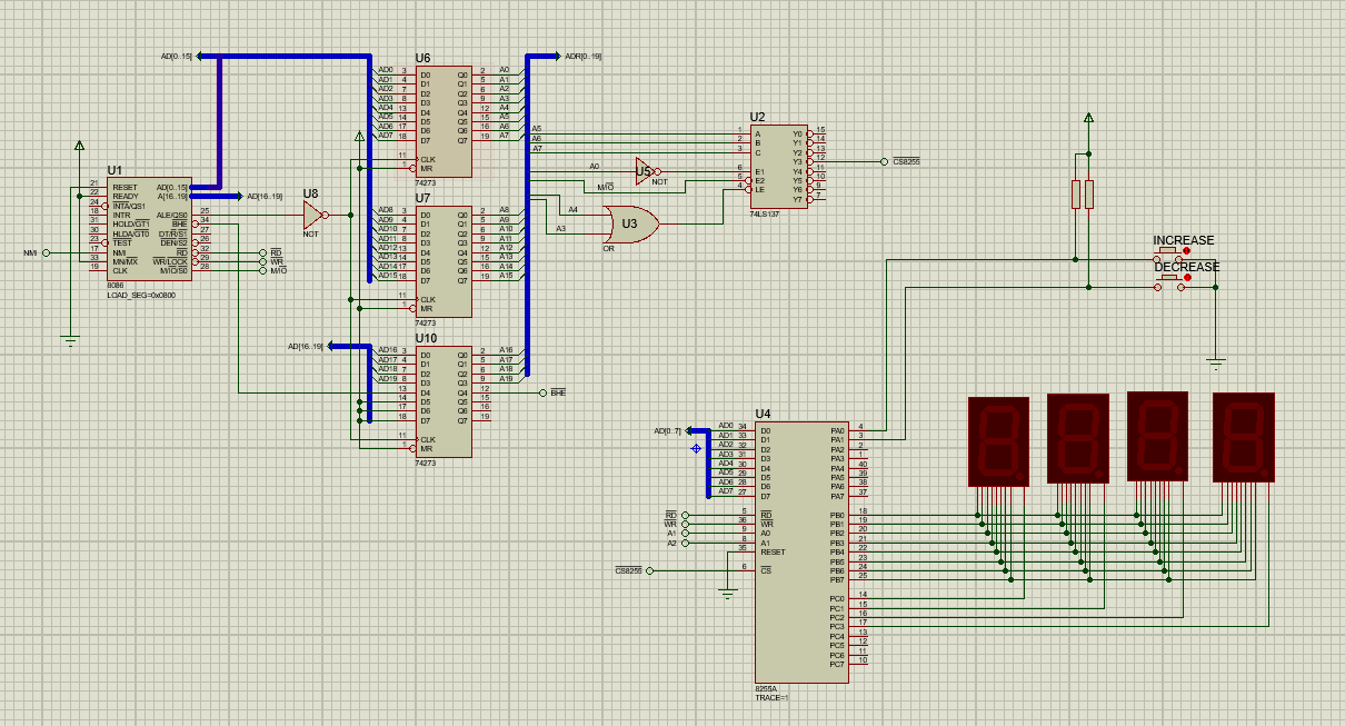
NM O A 21 22 24 18 31 30 23 33 19 U1 RESET READY INTOS1 INTR AD(0.15 8086 AD(0.151 A[16.19 ALEXOSO HOLD/GT1 BHE HLDAGTO HUDANGTO DT/RIS! TEST DENISS RD NM MNMX WR LOCK CLK MIC SO LOAD_SEG=0x0800 25 34 27 32 AD(16.19 ORD WR O MO U8 NOT |AD|16..19 AN ADC 3 AD1 4 ALQ 7 D2 D3 AD3 8 AD4 ACH 13 De ADA 14 D4 D5 D6 nt D7 JADE 17 ADT 18 11 ADE 3 NADO 4 AD10 7 AD118 AD1213 AD1314 AD1417 ATHE AD15 18 1518 11 ADIE 3 AD17 4 AD18 7 JAD19 8 13 1: 14 17 18 U6 DO D1 11 >CLK MR 74273 U7 Ino DO D1 DI D2 D3 D4 D5 D D7 >CLK MR 74273 U10 DO D1 nz D2 D3 D D4 D5 D6 D7 CLK MR 74273 00 01 0 03 12 0412 OS 06 07 00 01 M 02 03 2 5 A 6 As Ag A10 A11 03 12 A12 04 AT OS CE 07 04 55 05 07 A4 15 As 5 PS AO A A2 16 A6 19 A7 2 5 15 16 A14 19 A15 2 5 6 12 15 16 19 A1 A17 A1B A19 A5 AB A7 ADRID. 19 A3 OBE A4 AO 1 MO CR U3 NOT ADID. 71 CSART O * A2 O ADO 34 AD 33 AD 32 AD3 31 ADA 30 ADS 20 ADE 28 ADT 77 5 36 9 36 6 U2 A C E1 E2 LE 74LS137 U4 DO D1 D2 D3 D4 D5 Da D7 RD WR AO A1 RESET CS 82554 TRACE=1 YO 15 14 YI 13 Y2 DT2 Y3 YATO (is! YSR YE D 1752 PAD PA PA2 PA3 PAS PAG PA7 FA440 PCD PC1 PC2 PC3 4 3 2 PC4 PCS 11 PRO 18 19 FBI 20 FB2 21 FB3 - 22 FB42 FBS2 23 PB6 2 25 24 FB7 Pa PC6 PC7 39 38 37 14 15 16 17 13 12 11 10 CS8255 B A INCREASE Co DECREASE H o o
Step by Step Solution
3.44 Rating (154 Votes )
There are 3 Steps involved in it
a Critically damped system The steadystate error for a critically damped system can be calculated us... View full answer

Get step-by-step solutions from verified subject matter experts