

Question: Question Weight: 0 . 2 > Use the Graphical User Interface ( GUI ) CIV 2 2 6 3 _ A 6 Q 4 _
Question Weight: Use the Graphical User Interface GUI
CIVAQGUI.html
to enter your results. Enter only numbers in the GUI, no characters or symbols.
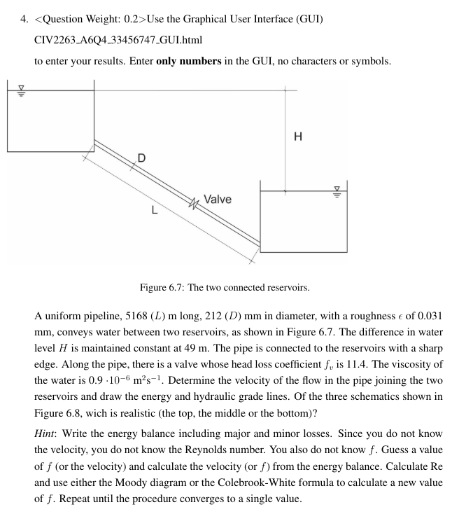
Figure : The two connected reservoirs.
A uniform pipeline, long, in diameter, with a roughness of
conveys water between two reservoirs, as shown in Figure The difference in water
level is maintained constant at The pipe is connected to the reservoirs with a sharp
edge. Along the pipe, there is a valve whose head loss coefficient is The viscosity of
the water is Determine the velocity of the flow in the pipe joining the two
reservoirs and draw the energy and hydraulic grade lines. Of the three schematics shown in
Figure wich is realistic the top, the middle or the bottom
Hint: Write the energy balance including major and minor losses. Since you do not know
the velocity, you do not know the Reynolds number. You also do not know Guess a value
of or the velocity and calculate the velocity or from the energy balance. Calculate
and use either the Moody diagram or the ColebrookWhite formula to calculate a new value
of Repeat until the procedure converges to a single value.
Step by Step Solution
There are 3 Steps involved in it
1 Expert Approved Answer
Step: 1 Unlock

Question Has Been Solved by an Expert!
Get step-by-step solutions from verified subject matter experts
Step: 2 Unlock
Step: 3 Unlock