

Question: Consider a Bridge Rectifier Circuit with Power Filter and Zener Diode at the Output as shown. For each set of Measured Voltages at Points
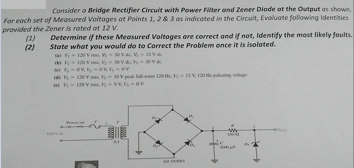
Consider a Bridge Rectifier Circuit with Power Filter and Zener Diode at the Output as shown. For each set of Measured Voltages at Points 1, 2 & 3 as indicated in the Circuit, Evaluate following Identities provided the Zener is rated at 12 V. (1) (2) Determine if these Measured Voltages are correct and if not, ldentify the most likely faults. State what you would do to Correct the Problem once it is isolated. (a) Vi = 120 V rms, V = 30 V de. V = 12 V de (b) V = 120 V rms, Vz = 30 V de, V3 = 30 V dc (c) V = 0 V, V 0 V, V, =0 V (d) V = 120 V rms, V2 = 30 V peak full-wave 120 Hz, Va = 12 V, 120 Hz pulsating voltage (e) V = 120 V mis, V = 9 V. V1 = 0V Power on R OVoun 120 V ae 330 2 5:1 D. 1000 F All IN4001 atis 00000 00000)
Step by Step Solution
3.46 Rating (159 Votes )
There are 3 Steps involved in it
4 120 Vrms Va 30Vdc V3 12 Vdc This could be true V2 30 V The measured voltages ... View full answer

Get step-by-step solutions from verified subject matter experts