

Question: Consider the half-wave rectifier circuit of Figure a. The circuit is driven by a triangular voltage source Vs (t) of amplitude V 0 = 9
Consider the half-wave rectifier circuit of Figure a. The circuit is driven by a triangular voltage source Vs (t) of amplitude V0 = 9 V as shown in Fig. 10.50. Assuming the diode to be ideal and for a resistor R = 1.5 k?:
a. Plot the resistor voltage VR (t).
b. Calculate the rms value of the resistor voltage.
c. Calculate the time-averaged power dissipation in the resistor.
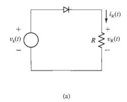
|iR() v,(1) DR(t) (a)
Step by Step Solution
★★★★★
3.25 Rating (163 Votes )
There are 3 Steps involved in it
1 Expert Approved Answer
Step: 1 Unlock

part a 90 UR t T4 72 374 ... View full answer
Question Has Been Solved by an Expert!
Get step-by-step solutions from verified subject matter experts
Step: 2 Unlock
Step: 3 Unlock
Document Format (1 attachment)
20-E-E-E-M (249).docx
120 KBs Word File