

Question: Question-2: Forced Aligned Counter Design a special purpose 4-bit counter required for any specific application. The special purpose 4-bit counter will counter in up/down mode;
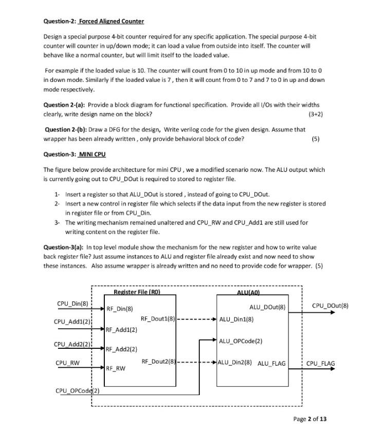
Question-2: Forced Aligned Counter Design a special purpose 4-bit counter required for any specific application. The special purpose 4-bit counter will counter in up/down mode; it can load a value from outside into itself. The counter will behave like a normal counter, but will limit itself to the loaded value. For example if the loaded value is 10. The counter will count from 0 to 10 in up mode and from 10 to 0 in down mode. Similarly if the loaded value is 7, then it will count from 0 to 7 and 7 to 0 in up and down mode respectively. Question 2-(a): Provide a block diagram for functional specification. Provide all I/Os with their widths clearly, write design name on the block? (3+2) Question 2-(b): Draw a DFG for the design, Write verilog code for the given design. Assume that wrapper has been already written, only provide behavioral block of code? (5) Question-3: MINI CPU The figure below provide architecture for mini CPU, we a modified scenario now. The ALU output which is currently going out to CPU_Dout is required to stored to register file. 1. Insert a register so that ALU_Dout is stored, instead of going to CPU_Dout. 2. Insert a new control in register file which selects if the data input from the new register is stored in register file or from CPU_Din. 3. The writing mechanism remained unaltered and CPU_RW and CPU_Add1 are still used for writing content on the register file. Question-3(a): In top level module show the mechanism for the new register and how to write value back register file? Just assume instances to ALU and register file already exist and now need to show these instances. Also assume wrapper is already written and no need to provide code for wrapper. (5) Register File (RO) CPU_Din(8) ALU(AO) ALU_DOut(8) ALU_Din1(8) CPU_DOut(8) RF_Din(8) RF_Dout18) RF_Add1(2) CPU_Add1(2) CPU_Add2(2): ALU_OP Code(2) RF_Add2(2) CPU_RW RF_Dout2(8) ALU_Din2(8) ALU_FLAG CPU_FLAG RF_RW CPU_OP Code(2) Page 2 of 13
Step by Step Solution
There are 3 Steps involved in it

Get step-by-step solutions from verified subject matter experts