

Question: Questions below based on figure above: Consider the Arithmetic Logic Unit (ALU) block diagram shown in Fig. 1(a). Each block is numbered in brackets, for
Questions below based on figure above:
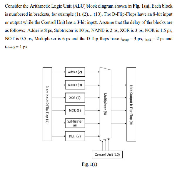
Consider the Arithmetic Logic Unit (ALU) block diagram shown in Fig. 1(a). Each block is numbered in brackets, for example (1), (2)... (10). The D-Flip-Flops have an 8-bit input or output while the Control Unit has a 3-bit input. Assume that the delay of the blocks are as follows: Adder is & ps, Subtracter is 10 ps, NAND is 2 ps, XOR is 3 ps, NOR is 1.5 ps, NOT is 0.5 ps, Multiplexer is 6 ps and the D flip-flops have tsctp = 3 ps, told = 2 ps and telk+Q=1 ps. 8-bit Input D Flip-Flop (1) Adcier (2) NAND (3) XOR (4) NCR (5) Subtracter NOT (7) Multiplexer (8) Control Unit (10) Fig. 1(a) 8-bit Output D Flip-Flop (9)
Step by Step Solution
3.39 Rating (165 Votes )
There are 3 Steps involved in it
Solutions Step 1 Calculating the delay for ... View full answer

Get step-by-step solutions from verified subject matter experts