

Question: Reference program from the CircuitPython Analog In exercise: begin{tabular}{l} hline #CircuitPython Demo (Part 1) import time import board from analogio import AnalogIn
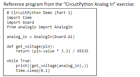
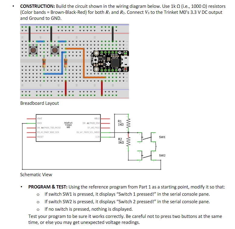
Reference program from the "CircuitPython Analog In" exercise: \begin{tabular}{l} \hline \#CircuitPython Demo (Part 1) \\ import time \\ import board \\ from analogio import AnalogIn \\ analog_in = AnalogIn(board.A1) \\ def get_voltage(pin): \\ return (pin.value * 3.3)/ 65535 \\ while True: \\ print (( get_voltage(analog_in), )) \\ time.sleep(o.1) \end{tabular} CONSTRUCTION: Build the circuit shown in the wiring diagram below. Use 1k (i.e., 1000 ) resistors (Color bands = Brown-Black-Red) for both R1 and R2. Connect VS to the Trinket M0's 3.3V DC output and Ground to GND. Breadboard Layout scnematc view - PROGRAM \& TEST: Using the reference program from Part 1 as a starting point, modify it so that: If switch SW1 is pressed, it displays "Switch 1 pressed!" in the serial console pane. - If switch SW2 is pressed, it displays "Switch 2 pressed!" in the serial console pane. - If no switch is pressed, nothing is displayed. Test your program to be sure it works correctly. Be careful not to press two buttons at the same time, or else you may get unexpected voltage readings
Step by Step Solution
There are 3 Steps involved in it

Get step-by-step solutions from verified subject matter experts