

Question: Revise the floating point addition unit presented in the textbook (Figure 3.15) to reflect the following requirements/restrictions: (1) add two numbers of same sign only
Revise the floating point addition unit presented in the textbook (Figure 3.15) to reflect the following requirements/restrictions: (1) add two numbers of same sign only (i.e. both positive or both negative), (2) replace the rounding unit with a truncation unit, i.e. modify Figure 3.15 by simplifying the normalization stage and control unit so there is no iteration back), (3) explicitly show how hidden one is handled. No need to trace data.
Design a floating point multiplication unit with overflow/underflow detection feature for multiplying two 32-bit floating point numbers in IEEE 754 format. An overflow detection will output 00 if no overflow/underflow; output 01 if overflow; 10 if underflow (note: you decide what is the input to this unit.) No need to show details of the overflow detection unit, i.e. make it a black box). When underflow occurs (i.e. the exponent of the result is too negative to fit the field), set both exponent and fraction parts with all 0s (i.e. the result is +0.0 or -0.0 in this case.) When there is overflow (i.e. the exponent of the result is too positive to fit the field), set the exponent to all 1s, and fraction to all 0s. In both cases the sign bit should be calculated as usual. Also use a truncation unit instead of the rounding method so that only one time/round of normalization needed. Show how the hidden 1 is handled. Trace your design with 3 sets of given data.
Expected Results
The following products are expected:
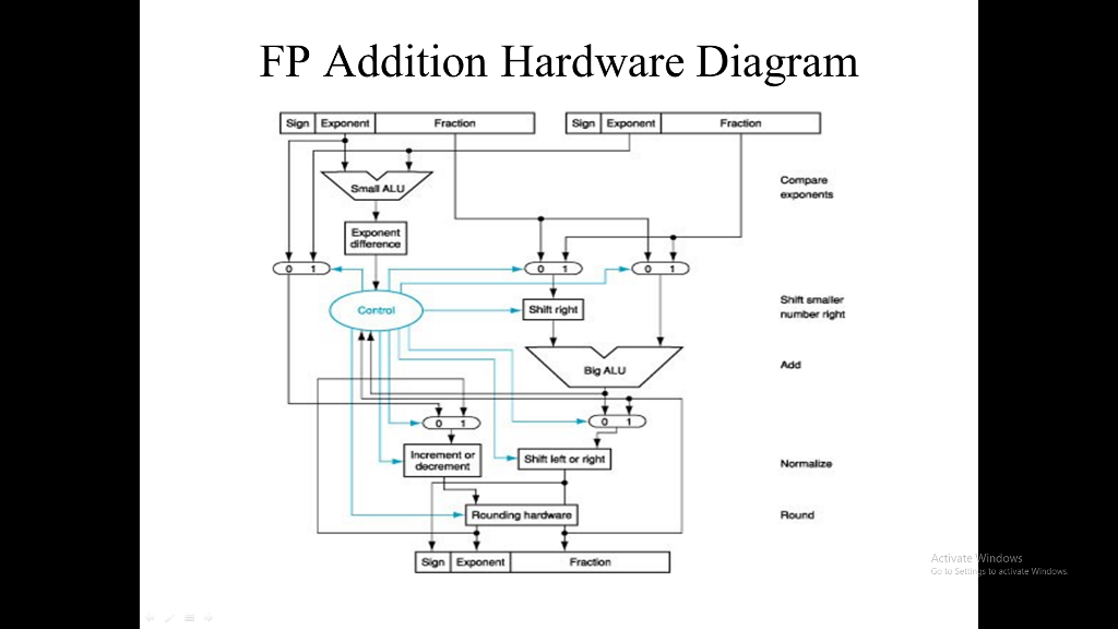
A neatly (computer or hand) drawn hardware diagrams (similar to Figure 3.15) for a simplified FP addition units as described in (A) above.
A neatly (computer or hand) drawn hardware diagram similar (in format) to the one in Figure 3.15 but performs the multiplication with overflow/underflow detection unit added. You may assume an integer multiplication unit available to use (i.e. no need to build up the integer multiplication unit using ALU, registers, etc.) For each functional unit, write a meaningful name on it, i.e. ALU, integer_multiplier (or i-mult), AND/OR/XOR/NOR gate, shift left/right,
For the FP multiplication unit, trace the test data (a), (b), and (c). Here tracing a test data set means that you walk through the diagram and show the input/output of each major functional unit in the diagram. For each test case, you may make a copy of your diagram, and put tracing data along each functional unit of your diagram. The following sample tracing gives you a rough idea of the input/output data for each functional unit (note: functional units may vary.)
Multiplication unit testing data sets (note: check binary representation)
(a) -1.10110110101101011010111 x 210 multiplies 1.11000000000000000000000 x 2-4
Input data: 11000100110110110101101011010111
00111101111000000000000000000000
(b) 1.10110110101101011010111 x 2-96 multiples -1.11000000000000000000000 x 2-74
Input data: 00001111110110110101101011010111
10011010111000000000000000000000
(c) -1.10110110101101011010111 x 255 multiples -1.11000000000000000000000 x 272
Input data: 11011011010110110101101011010111
11100011111000000000000000000000
(Note: Please verify the binary representation of these FP data. If you spot any error please make correction and comment it on your cover page.)
FP Addition Hardware Diagram Sign Exponent FractionnExonentFroacion Compare Small ALU Exponent Shift smaler number right Control Shit right Add Big ALU Increment or Shift left or right Round Activate to Setti indows s to activate Windons Sign Exponent Fracton
Step by Step Solution
There are 3 Steps involved in it

Get step-by-step solutions from verified subject matter experts