

Question: Rount-PT Rogero VLAN 10 PC-PT PCA VLAN 40 PC-PT PC15 n VLAN 20 PC-PT PCS PC-PT PC14 VLAN 30 PC PT PC13 VLAN 30 PC-PT
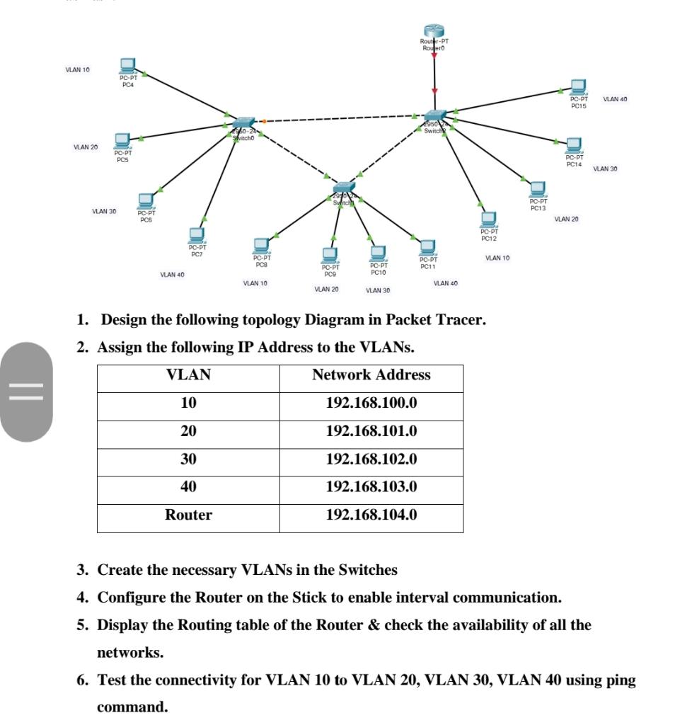
Rount-PT Rogero VLAN 10 PC-PT PCA VLAN 40 PC-PT PC15 n VLAN 20 PC-PT PCS PC-PT PC14 VLAN 30 PC PT PC13 VLAN 30 PC-PT PCS VLAN 20 PC-PT PC12 PC-PT PC7 PC-PT PCS VLAN 10 PC-DT PC11 PC.PT PC10 PC-PT PC9 VLAN 40 VLAN 10 VLAN 40 VLAN 20 VLAN 30 1. Design the following topology Diagram in Packet Tracer. 2. Assign the following IP Address to the VLANs. VLAN Network Address = 10 192.168.100.0 20 192.168.101.0 30 192.168.102.0 40 192.168.103.0 Router 192.168.104.0 3. Create the necessary VLANs in the Switches 4. Configure the Router on the Stick to enable interval communication. 5. Display the Routing table of the Router & check the availability of all the networks. 6. Test the connectivity for VLAN 10 to VLAN 20, VLAN 30, VLAN 40 using ping command
Step by Step Solution
There are 3 Steps involved in it

Get step-by-step solutions from verified subject matter experts