

Question: SCHEMATICS Figure 6 . 1 PROCEDURE Voltage Application Consider the dual supply circuit of Figure 6 . 1 using V 1 = 1 0 volts,
SCHEMATICS
Figure
PROCEDURE
Voltage Application
Consider the dual supply circuit of Figure using volts, volts, and To find the voltage from node A to ground, superposition may be used. Each source is considered by itself. First consider source V by assuming that V is replaced with its internal resistance a short Determine the voltage at node A using standard seriesparallel techniques and record it in Table Make sure to indicate the polarity. Repeat the process using V while shorting V Finally, sum these two voltages and record in Table
To verify the superposition theorem, the process may be implemented directly by measuring the contributions. Build the circuit of Figure with the values specified in step however, replace V with a short. Do not simply place a shorting wire across source V This will overload the power supply.
Measure the voltage at node A and record in Table Be sure to note the polarity.
Remove the shorting wire and insert source V Also, replace source V with a short. Measure the voltage at node A and record in Table Be sure to note the polarity.Remove the shorting wire and reinsert source V Both sources should now be in the circuit. Measure the voltage at node A and record in Table Be sure to note the polarity. Determine and record the deviations between theory and experimental results.
Current and Power Application
Consider the dual supply circuit of Figure using V volts, V volts, and To find the current through R flowing from node A to B superposition may be used. Each source is again treated independently with the remaining sources replaced with their internal resistances. Calculate the current through R first considering V and then considering V Sum these results and record the three values in Table
Assemble the circuit of Figure using the values specified. Replace source V with a short and measure the current through R Be sure to note the direction of flow and record the result in Table
Replace the short with source V and swap source V with a short. Measure the current through R Be sure to note the direction of flow and record the result in Table
Remove the shorting wire and reinsert source V Both sources should now be in the circuit. Measure the current through R and record in Table Be sure to note the direction. Determine and record the deviations between theory and experimental results.
Power is not a linear function as it is proportional to the square of either voltage or current. Consequently, superposition should not yield an accurate result when applied directly to power. Based on the measured currents in Table calculate the power in R using Vonly and Vonly and record the values in Table Adding these two powers yields the power as predicted by superposition. Determine this value and record it in Table The true power in R may be determined from the total measured current flowing through it Using the experimental current measured when bothV and V were active Table determine the power in R and record it in Table DATA TABLES
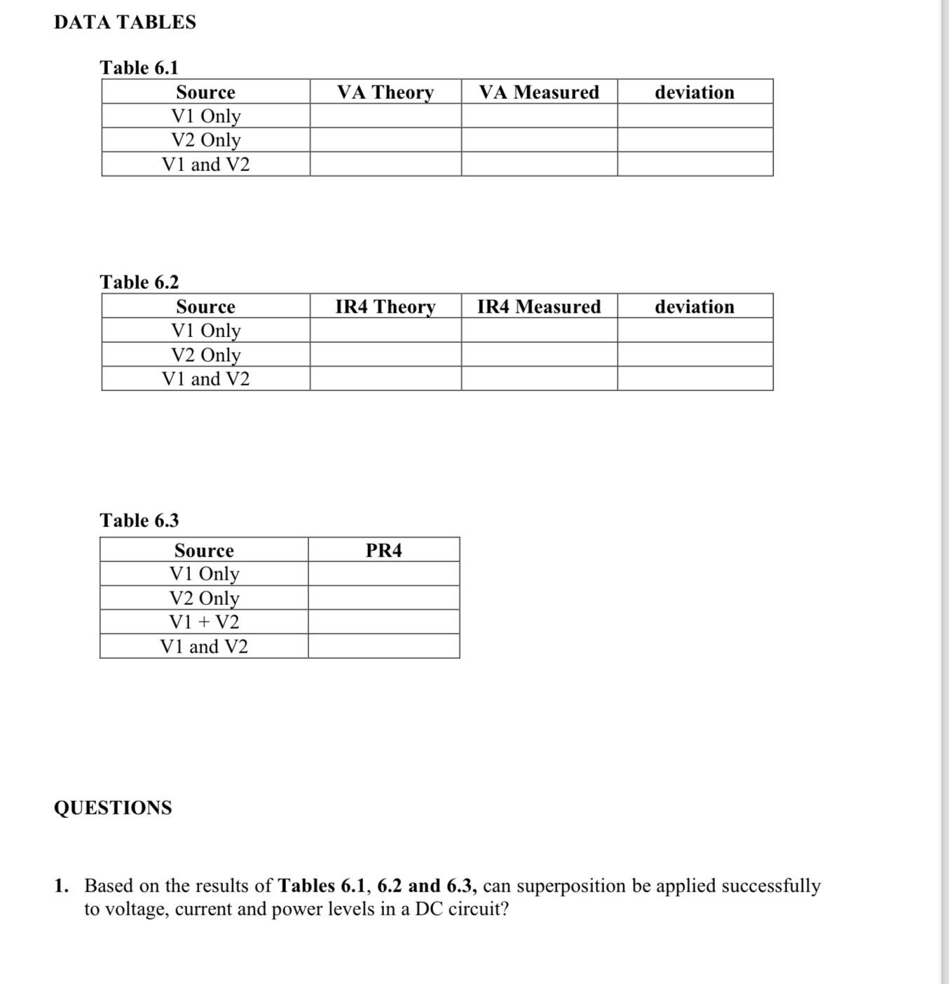
Table
tableSourceVA Theory,VA Measured,deviationV Only,,,V Only,,,V and V
Table
tableSourceIR Theory,IR Measured,deviationV Only,,,V Only,,,V and V
Table
tableSourcePRV Only,V Only,V VV and V
QUESTIONS
Based on the results of Tables and can superposition be applied successfully to voltage, current and power levels in a DC circuit?
Step by Step Solution
There are 3 Steps involved in it
1 Expert Approved Answer
Step: 1 Unlock

Question Has Been Solved by an Expert!
Get step-by-step solutions from verified subject matter experts
Step: 2 Unlock
Step: 3 Unlock