

Question: Scher Procedure AC Load Line and Power Analysis Consider the circuit of Figure 1 using V c c = 5 volts, Vee = - 1
Scher
Procedure
AC Load Line and Power Analysis
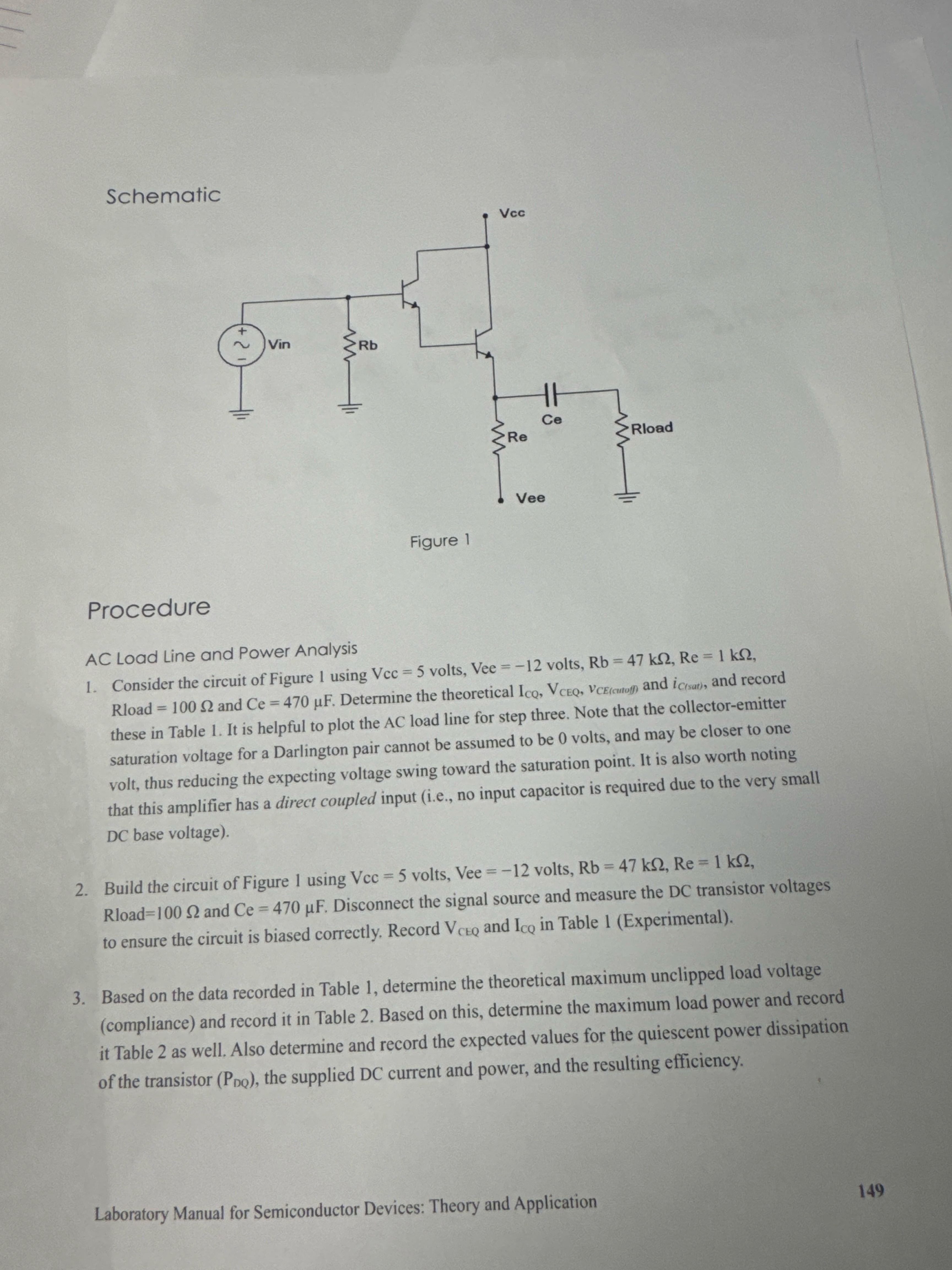
Consider the circuit of Figure using volts, Vee volts, Rload and Determine the theoretical and and record these in Table It is helpful to plot the AC load line for step three. Note that the collectoremitter saturation voltage for a Darlington pair cannot be assumed to be volts, and may be closer to one volt, thus reducing the expecting voltage swing toward the saturation point. It is also worth noting that this amplifier has a direct coupled input ie no input capacitor is required due to the very small DC base voltage
Build the circuit of Figure using volts, Vee volts, Rload and Disconnect the signal source and measure the DC transistor voltages to ensure the circuit is biased correctly. Record and in Table Experimental
Based on the data recorded in Table determine the theoretical maximum unclipped load voltage compliance and record it in Table Based on this, determine the maximum load power and record it Table as well. Also determine and record the expected values for the quiescent power dissipation of the transistor the supplied DC current and power, and the resulting efficiency.
Laboratory Manual for Semiconductor Devices: Theory and Application
Please solve for Vceq and Iq
Step by Step Solution
There are 3 Steps involved in it
1 Expert Approved Answer
Step: 1 Unlock

Question Has Been Solved by an Expert!
Get step-by-step solutions from verified subject matter experts
Step: 2 Unlock
Step: 3 Unlock