

Question: SECTION B: The structure shown in Figure 2 was modelled using three plane strain triangular shaped elements. The loading and corresponding boundary conditions are shown
SECTION B:
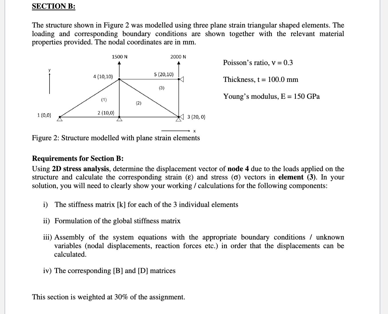
The structure shown in Figure was modelled using three plane strain triangular shaped elements. The loading and corresponding boundary conditions are shown together with the relevant material properties provided. The nodal coordinates are in mm
Poisson's ratio, v
Thickness, mathrmtmathrm~mm
Young's modulus, mathrmEmathrmGPa
Figure : Structure modelled with plane strain elements
Requirements for Section B:
Using D stress analysis, determine the displacement vector of node due to the loads applied on the structure and calculate the corresponding strain boldsymbolvarepsilon and stress sigma vectors in element In your solution, you will need to clearly show your working calculations for the following components:
i The stiffness matrix k for each of the individual elements
ii Formulation of the global stiffness matrix
iii Assembly of the system equations with the appropriate boundary conditions unknown variables nodal displacements, reaction forces etc. in order that the displacements can be calculated.
iv The corresponding B and D matrices
Step by Step Solution
There are 3 Steps involved in it
1 Expert Approved Answer
Step: 1 Unlock

Question Has Been Solved by an Expert!
Get step-by-step solutions from verified subject matter experts
Step: 2 Unlock
Step: 3 Unlock