

Question: Set up the MEB between Points 3 and 4, and calculate the pressure drop (P3 P4) for that section. Calculate absolute pressures P1, P2, P3,
Set up the MEB between Points 3 and 4, and calculate the pressure drop (P3 P4) for that section.
Calculate absolute pressures P1, P2, P3, and convert these to liquid height (h) in meters for the columns shown in the Illustration. Dont forget to account for the atmospheric pressure, P4.
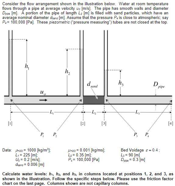
Consider the flow arrangement shown in the illustration below. Water at room temperature flows through a pipe at average velocity wo [m/s]. The pipe has smooth walls and diameter Dpipe [m]. A portion of the pipe of length L2 [m] is filled with sand particles, which have an average nominal diameter dsena [m]. Assume that the pressure P. is close to atmospheric; say Pe= 100,000 [Pa]. These piezometric pressure measuring") tubes are not closed at the top. h h h d sand hz D pipe u. L L [1] [2] [3] [4] P, P. = Data: 2-20 = 1000 [kg/m ]; -20 = 0.001 [kg/ms] Bed Voidage & = 0.4; L1 = 225 [m] L2 = 0.35 [m] Ls = 90 [m] Un = 0.2 [m/s]; Ps= 100,000 [Pa] Doipe = 0.3 [m] dsana = 0.006 [m] Calculate water levels: h1, h2, and hs, in columns located at positions 1, 2, and 3, as shown in the illustration. Follow the specific steps below. Please use the friction factor chart on the last page. Columns shown are not capillary columns
Step by Step Solution
There are 3 Steps involved in it

Get step-by-step solutions from verified subject matter experts