

Question: Short answer ( 2 0 points ) As shown in the left figure, a force of size P in the x - direction is applied
Short answer points
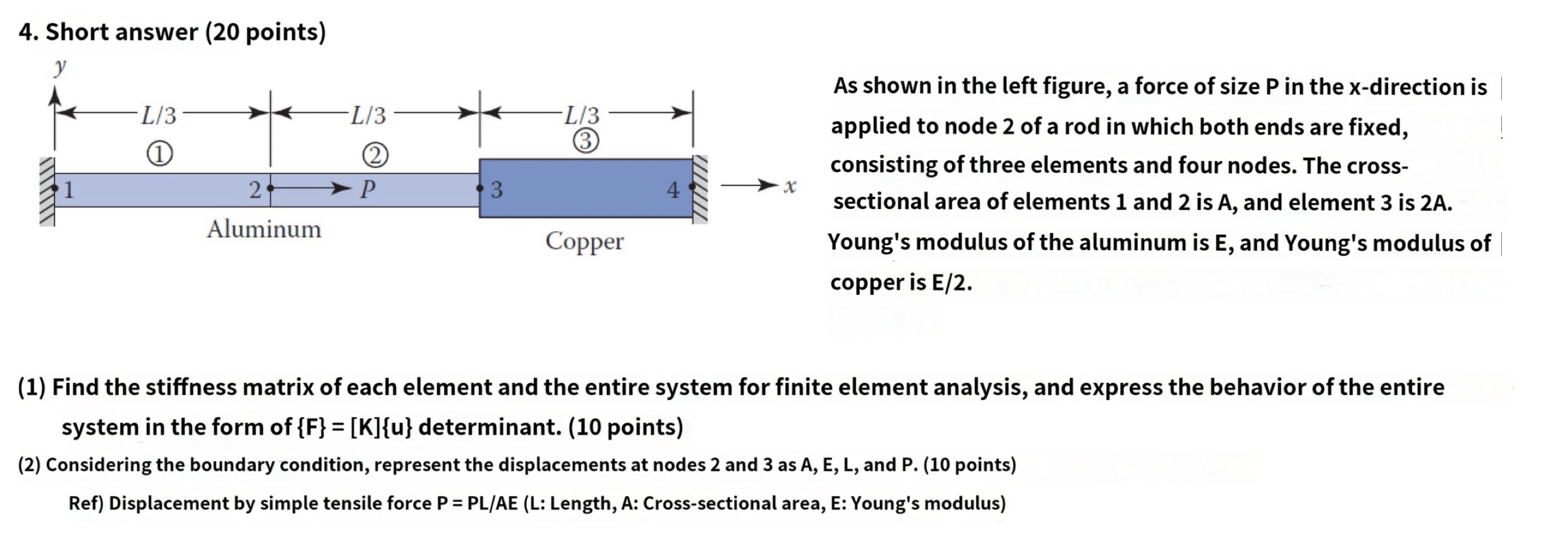
As shown in the left figure, a force of size in the direction is applied to node of a rod in which both ends are fixed, consisting of three elements and four nodes. The crosssectional area of elements and is and element is Young's modulus of the aluminum is E and Young's modulus of copper is
Find the stiffness matrix of each element and the entire system for finite element analysis, and express the behavior of the entire system in the form of determinant. points
Considering the boundary condition, represent the displacements at nodes and as A E L and P points
Ref Displacement by simple tensile force P PLAE L: Length, A: Crosssectional area, E: Young's modulus
Step by Step Solution
There are 3 Steps involved in it
1 Expert Approved Answer
Step: 1 Unlock

Question Has Been Solved by an Expert!
Get step-by-step solutions from verified subject matter experts
Step: 2 Unlock
Step: 3 Unlock