

Question: For the circuit shown in Figure 1a, Let RA= Rc = Rp = 0.1 KQ. A Ro RD +10 RA RB VB 10 K
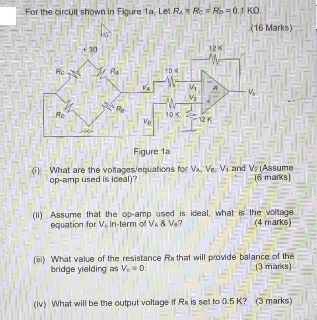
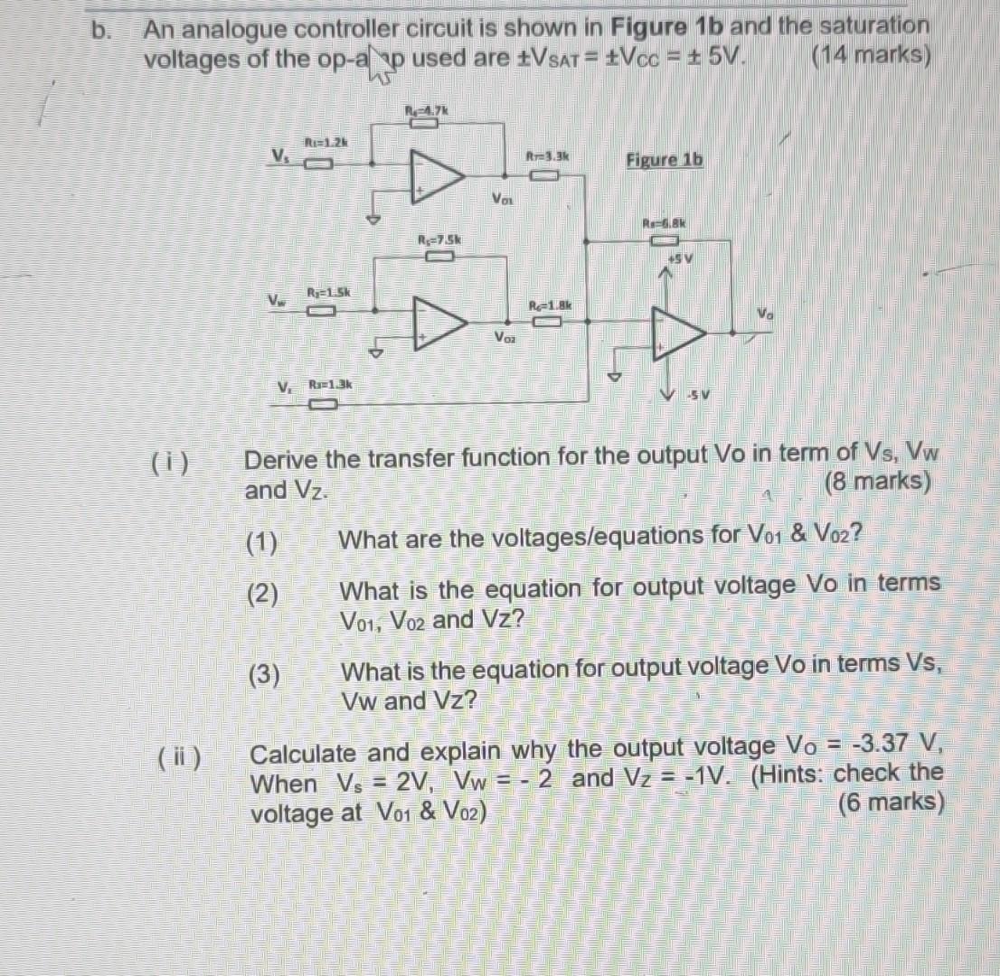
For the circuit shown in Figure 1a, Let RA= Rc = Rp = 0.1 KQ. A Ro RD +10 RA RB VB 10 K W 10 K 12 K 12 K (16 Marks) Vo 179 Figure 1a (i) What are the voltages/equations for VA, VB, V and V (Assume op-amp used is ideal)? (6 marks) (ii) Assume that the op-amp used is ideal, what is the voltage equation for Vo in-term of VA & VB? (4 marks) (iii) What value of the resistance Re that will provide balance of the bridge yielding as V. = 0. (3 marks) (iv) What will be the output voltage if Re is set to 0.5 K? (3 marks) b. An analogue controller circuit is shown in Figure 1b and the saturation voltages of the op-ap used are +VSAT = VCC = 5V. (14 marks) (i) (ii) V V Ri=1.2k V, R=1.3k (1) (2) R-1-5k (3) R-4.7k R=7.5k VOL Voz R-3.3k Re-1.8k Figure 1b Re-6.8k +5V Derive the transfer function for the output Vo in term of Vs, Vw and Vz. (8 marks) SV What are the voltages/equations for V01 & Vo2? What is the equation for output voltage Vo in terms V01, Vo2 and Vz? What is the equation for output voltage Vo in terms Vs, Vw and Vz? Calculate and explain why the output voltage Vo = -3.37 V, When Vs = 2V, Vw = -2 and V = -1V. (Hints: check the (6 marks) voltage at Vo1 & V02)
Step by Step Solution
3.48 Rating (168 Votes )
There are 3 Steps involved in it

Get step-by-step solutions from verified subject matter experts