

The following table gives the state of a J-K flip-flow after receipt of the nth clock pulse:
Question:
The following table gives the state of a J-K flip-flow after receipt of the nth clock pulse:
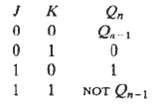
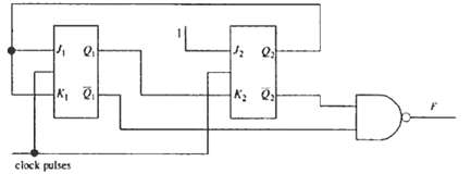
For the circuit shown in figure, deduce how the output F changes on receipt of a regular train of clock pulses, given that the initial state is Q1 = Q2 =0
Fantastic news! We've Found the answer you've been seeking!
Step by Step Answer:
The output F is NOT Q 1 NAND NOT Q 2 which by Do Morgans theorem us Q 1 Q 2 0 The output F i...View the full answer

Answered By
Prudhvi Doddi
I am a computer science graduate with first class. I have worked in online tutoring platform and tutored many students across the globe on various programming languages like c,java,c#, python . Then i have also done post graduate diploma in advanced computing. Currently i am working as a software engineer , working on c#, java,.net technologies.
0 Reviews
10+ Question Solved
Related Book For 
Question Posted:
