

Question: Solve in paper . . . . A single line diagram of a 3 - phase power system is shown in Figure Q 2 .
Solve in paper A single line diagram of a phase power system is shown in Figure Q Positive, negative and zero sequence impedances of the system are shown in Table Q
Table Q
tableNetwork Components,XpuXpuXo puGenerator Generator Transformer Transformer Transmission line
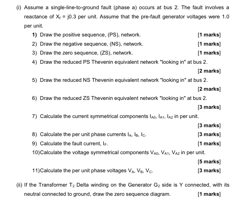
The neutral of the generators & are solidly grounded. The neutral of the Y winding of Transformer on the generator side is grounded through a reactance of per unit. The neutral of the winding of Transformer on the Bus side is grounded through a resistance of per unit. Transformers connections are shown in Figure Qai Assume a singlelinetoground fault phase a occurs at bus The fault involves a reactance of per unit. Assume that the prefault generator voltages were per unit.
Draw the positive sequence, PS network.
marks
Draw the negative sequence, NS network.
marks
Draw the zero sequence, ZS network.
marks
Draw the reduced PS Thevenin equivalent network "looking in at bus
marks
Draw the reduced NS Thevenin equivalent network "looking in at bus
marks
Draw the reduced ZS Thevenin equivalent network "looking in at bus
marks
Calculate the current symmetrical components in per unit.
marks
Calculate the per unit phase currents
marks
Calculate the fault current,
marks
Calculate the voltage symmetrical components in per unit.
marks
Calculate the per unit phase voltages
marks
ii If the Transformer Delta winding on the Generator side is connected, with its neutral connected to ground, draw the zero sequence diagram.
marks
Step by Step Solution
There are 3 Steps involved in it
1 Expert Approved Answer
Step: 1 Unlock

Question Has Been Solved by an Expert!
Get step-by-step solutions from verified subject matter experts
Step: 2 Unlock
Step: 3 Unlock