

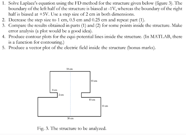
Question: Solve Laplace's equation using the FD method for the structure given below ( figure 3 ) . The boundary of the left half of the
Solve Laplace's equation using the FD method for the structure given below figure The
boundary of the left half of the structure is biased at whereas the boundary of the right
half is biased at Use a step size of in both dimensions.
Decrease the step size to and and repeat part
Compare the results obtained in parts and for some points inside the structure. Make
error analysis a plot would be a good idea
Produce contour plots for the equipotential lines inside the structure. In MATLAB, there
is a function for contouring.
Produce a vector plot of the electric field inside the structure bonus marks
Fig. The structure to be analyzed.
Step by Step Solution
There are 3 Steps involved in it
1 Expert Approved Answer
Step: 1 Unlock

Question Has Been Solved by an Expert!
Get step-by-step solutions from verified subject matter experts
Step: 2 Unlock
Step: 3 Unlock