

Question: Solve the problem on this homework assignment using a combination of handwritten calculations and EXCEL. You are required to use Excel when plotting pump curves
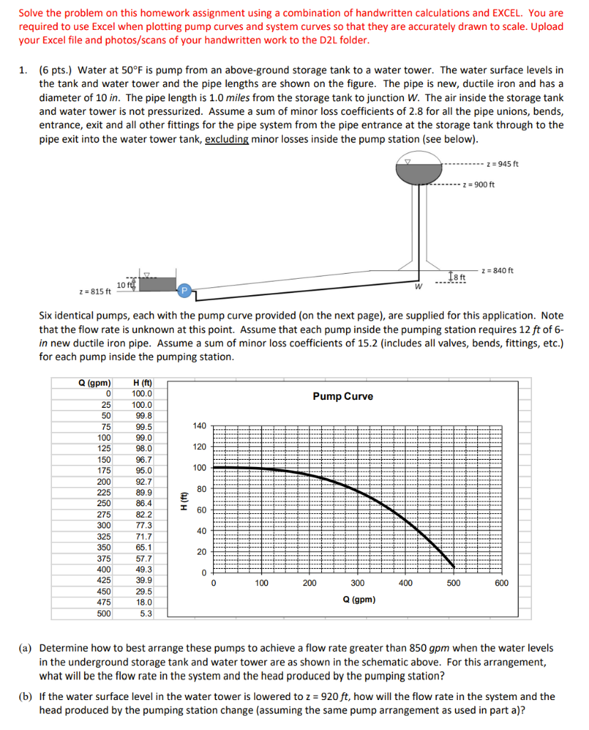
Solve the problem on this homework assignment using a combination of handwritten calculations and EXCEL. You are required to use Excel when plotting pump curves and system curves so that they are accurately drawn to scale. Upload your Excel file and photos/scans of your handwritten work to the D2L folder. 1. (6 pts.) Water at 50F is pump from an above-ground storage tank to a water tower. The water surface levels in the tank and water tower and the pipe lengths are shown on the figure. The pipe is new, ductile iron and has a diameter of 10 in. The pipe length is 1.0 miles from the storage tank to junction W. The air inside the storage tank and water tower is not pressurized. Assume a sum of minor loss coefficients of 2.8 for all the pipe unions, bends, entrance, exit and all other fittings for the pipe system from the pipe entrance at the storage tank through to the pipe exit into the water tower tank, excluding minor losses inside the pump station (see below). z = 945 ft z = 900 ft Z 18 ft 2 = 840 ft 10 ft ... 2=815 ft Six identical pumps, each with the pump curve provided on the next page), are supplied for this application. Note that the flow rate is unknown at this point. Assume that each pump inside the pumping station requires 12 ft of 6- in new ductile iron pipe. Assume a sum of minor loss coefficients of 15.2 (includes all valves, bends, fittings, etc.) for each pump inside the pumping station. Pump Curve 140 120 100 80 Q (gpm) 0 25 50 75 100 125 150 175 200 225 250 275 300 325 350 375 400 425 450 475 500 H (ft) 100.0 100.0 99.8 99.5 99.0 98.0 96.7 95.0 92.7 89.9 86.4 82.2 77.3 71.7 65.1 57.7 49.3 39.9 29.5 18.0 5.3 ) H(ft) I 60 40 20 0 0 100 200 300 400 500 600 Q (gpm) (a) Determine how to best arrange these pumps to achieve a flow rate greater than 850 gpm when the water levels in the underground storage tank and water tower are as shown in the schematic above. For this arrangement, what will be the flow rate in the system and the head produced by the pumping station? (b) If the water surface level in the water tower is lowered to z = 920 ft, how will the flow rate in the system and the head produced by the pumping station change (assuming the same pump arrangement as used in part a)
Step by Step Solution
There are 3 Steps involved in it

Get step-by-step solutions from verified subject matter experts