

Question: Starting from this lab experiment, you will be using the following startup code to replace the previous one: ; Standard definitions of Mode bits and
Starting from this lab experiment, you will be using the following startup code to replace the previous one: ; Standard definitions of Mode bits and Interrupt (I & F) flags in PSR s Mode_USR EQU 0x10 I_Bit EQU 0x80 ; when I bit is set, IRQ is disabled F_Bit EQU 0x40 ; when F bit is set, FIQ is disabled ;Defintions of User Mode Stack and Size USR_Stack_Size EQU 0x00000100 SRAM EQU 0X40000000 Stack_Top EQU SRAM+USR_Stack_Size
AREA RESET, CODE, READONLY ;make sure RESET is capitalized ENTRY ARM IMPORT user_code
VECTORS
LDR PC,Reset_Addr LDR PC,Undef_Addr LDR PC,SWI_Addr LDR PC,PAbt_Addr
California State University, Northridge ECE425L, Spring 2023 ECE Department By: Neda Khavari
2
LDR PC,DAbt_Addr NOP LDR PC,IRQ_Addr LDR PC,FIQ_Addr Reset_Addr DCD Reset_Handler Undef_Addr DCD UndefHandler SWI_Addr DCD SWIHandler PAbt_Addr DCD PAbtHandler DAbt_Addr DCD DAbtHandler
DCD 0 IRQ_Addr DCD IRQHandler FIQ_Addr DCD FIQHandler SWIHandler B SWIHandler PAbtHandler B PAbtHandler DAbtHandler B DAbtHandler IRQHandler B IRQHandler FIQHandler B FIQHandler UndefHandler B UndefHandler Reset_Handler ;initialize the stack, full descending LDR SP, =Stack_Top ; Enter User Mode with interrupts enabled MOV r14, #Mode_USR BIC r14,r14,#(I_Bit+F_Bit) MSR cpsr_c, r14 ;load start address of user code into PC LDR pc, =user_code END
New assembly lines are added to the previous startup code you used in the previous lab experiments, and they are enclosed in boxes. You may use the same name for this code as mystartup.s. In addition, you need to pay attend to the following formatting: The AREA name for the above code is RESET, which is capitalized The AREA name for your own code needs to be lower case The label for the first line of your own code should be user_code
Several branch instructions are available for ARM7TDMI processor; in this lab we only practice the following type of instructions: B
B without any suffix is the simplest branch. When this instruction is executed, the ARM processor will load the destination address to its program counter, and start executing from there. The actual execution of this branch instruction can be examined using the debugging tool in the Keil Vision IDE. In your lab report, describe in detail how the branch instructions used in your program are actually executed. B can be executed unconditionally and conditionally. The conditional execution is done by adding a condition code as suffix. The condition codes are listed in Table 8.1 on page 129 of the textbook. The following conditional branches may be used in this lab: BEQ branch if equal or zero; branch if the condition code flag Z = 1 BNE branch if not equal or zero; branch if Z = 0 BGE branch if the signed result is greater than or equal to zero; the result from the previous instruction will be interpreted by this instruction to be signed numbers. BGT branch if the signed result is greater than zero; the result from the previous instruction will be interpreted by this instruction to be signed numbers. 2.3 LOOPS We have built the simplest loop (endless or unconditionally) in previous lab experiments, which is
stop B stop
However, most of loops need to check if a terminating condition is met. A loop in C language is shown below with a terminating condition:
#define COUNT_VAL 10000; int i; for (i=0; i
where the code increase the counter i from 0 to 10000, then stop. In assembly language, we prefer counting down than counting up, that is #define COUNT_VAL 10000; int i; for (i= COUNT_VAL; i
This piece of code can be used to implement a delay. As one part of your pre-lab, you will write equivalent code in ARM assembly to implement both a counting-up delay and a counting-down delay. Note that S could be appended to many ARM instructions to influence the condition code flags. For example,
SUBS r0, r1,r0 ;r0=r1-r0, and set the condition code flags
;according to the results
ADDS r0, r1,r2 ;r0=r1+r2, and set the condition code flags
;according to the results With S, SUB and ADD instructions dont affect the condition code flags. 2.4 DATA SECTION Note that addresses ranging from 0 to 0x7FFFF are mapped to the on-chip 512 KB flash memory, which cannot be modified by the store instructions such as STR. To allocate RAM memory locations to your code or data, you may use, for example:
AREA mydata, DATA, READWRITE sum DCD 0 ;reserve 4-byte location for sum with initial value 0 result SPACE 8 ;reserve 8-bytes for result with initial value 0
Urgent Please help! Also email me tanklessleech.business- g m a i l. com
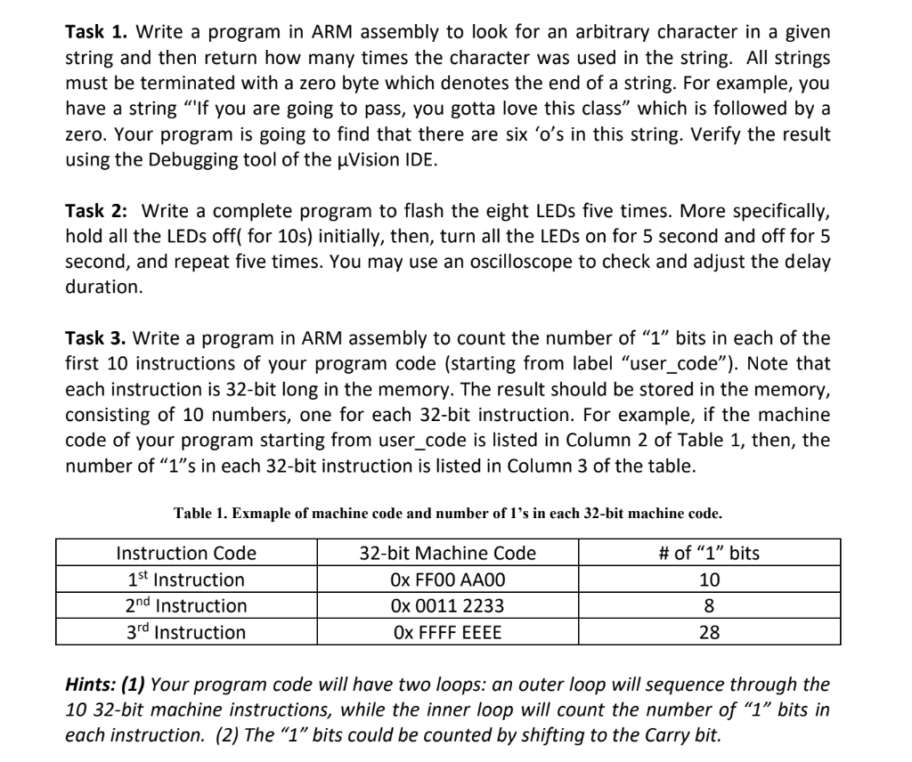
Task 1. Write a program in ARM assembly to look for an arbitrary character in a given string and then return how many times the character was used in the string. All strings must be terminated with a zero byte which denotes the end of a string. For example, you have a string "'If you are going to pass, you gotta love this class" which is followed by a zero. Your program is going to find that there are six ' o 's in this string. Verify the result using the Debugging tool of the Vision IDE. Task 2: Write a complete program to flash the eight LEDs five times. More specifically, hold all the LEDs off( for 10s) initially, then, turn all the LEDs on for 5 second and off for 5 second, and repeat five times. You may use an oscilloscope to check and adjust the delay duration. Task 3. Write a program in ARM assembly to count the number of " 1 " bits in each of the first 10 instructions of your program code (starting from label "user_code"). Note that each instruction is 32-bit long in the memory. The result should be stored in the memory, consisting of 10 numbers, one for each 32-bit instruction. For example, if the machine code of your program starting from user_code is listed in Column 2 of Table 1, then, the number of " 1 "s in each 32 -bit instruction is listed in Column 3 of the table. Table 1. Exmaple of machine code and number of 1's in each 32-bit machine code. Hints: (1) Your program code will have two loops: an outer loop will sequence through the 10 32-bit machine instructions, while the inner loop will count the number of "1" bits in each instruction. (2) The " 1 " bits could be counted by shifting to the Carry bit
Step by Step Solution
There are 3 Steps involved in it

Get step-by-step solutions from verified subject matter experts