

Question: Step 1 : Assign static IP information to the PC interfaces. a . Configure the IP address, subnet mask, and default gateway settings on PC
Step : Assign static IP information to the PC interfaces.
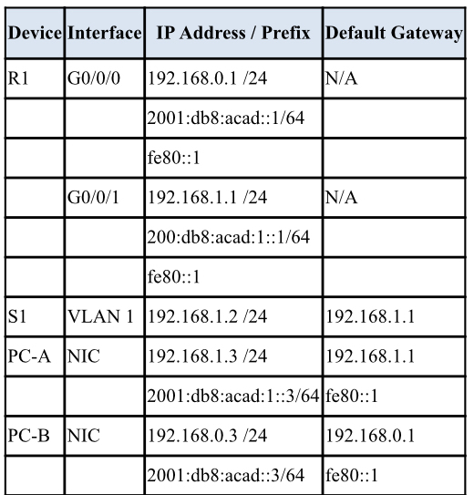
a Configure the IP address, subnet mask, and default gateway settings on PCA
b Configure the IP address, subnet mask, and default gateway settings on PCB
c Ping PCB from a command prompt window on PCA
Note: If pings are not successful, the Windows Firewall may need to be turned off.
Why were the pings not successful?
Step : Configure the router.
a Console into the router and enable privileged EXEC mode.
b Enter configuration mode.
c Assign a device name to the router.
d Disable DNS lookup to prevent the router from attempting to translate incorrectly entered commands as though they were host names.
e Assign class as the privileged EXEC encrypted password.
f Assign cisco as the console password and enable login
g Assign cisco as the VTY password and enable login
h Encrypt the plaintext passwords.
Create a banner that warns anyone accessing the device that unauthorized access is prohibited.
Configure and activate both interfaces on the router.
k Configure an interface description for each interface indicating which device is connected to it
To enable IPv routing, enter the command ipv unicastrouting.
Rconfig# ipv unicastrouting
m Save the running configuration to the startup configuration file.
Set the clock on the router.
Note: Use the question mark to help with the correct sequence of parameters needed to execute this command.
o Ping PCB from a command prompt window on PCA
o Ping PCB from a command prompt window on PCA
Note: If pings are not successful, the Windows Firewall may need to be turned off.
Were the pings successful? Explain.
Step : Configure the switch.
In this step, you will configure the hostname, the VLAN interface and its default gateway.
a Console into the switch and enable privileged EXEC mode.
b Enter configuration mode.
c Assign a device name to the switch.
d Disable DNS lookup to prevent the router from attempting to translate incorrectly entered commands as though they were host names.
e Configure and activate the VLAN interface on the switch S
f Configure the default gateway for the switch S
g Save the running configuration to the startup configuration file.
Step : Verify connectivity endtoend connectivity.
a From PCA ping PCB
b From S ping PCB
All the pings should be successful.
Part : Display Device Information
In Part you will use show commands to retrieve interface and routing information from the router and switch.
Step : Display the routing table on the router.
a Use the show ip route command on the router R to answer the following questions.
What code is used in the routing table to indicate a directly connected network?
How many route entries are coded with a C code in the routing table?
What interface types are associated to the C coded routes?
b Use the show ipv route command on router R to display the IPv routes.
Step : Display interface information on the router R
a Use the show ip interface to answer the following questions.
What is the operational status of the G interface?
What is the Media Access Control MAC address of the G interface?
How is the Internet address displayed in this command?
b For the IPv information, enter the show ipv interface interface command.
Step : Display a summary list of the interfaces on the router and switch.
There are several commands that can be used to verify an interface configuration. One of the most useful of these is the show ip interface brief command. The command output displays a summary list of the interfaces on the device and provides immediate feedback to the status of each interface.
a Enter the show ip interface brief command on the router R
R# show ip interface brief
b To see the IPv interface information, enter the show ipv interface brief command on R
R# show ipv interface brief
c Enter the show ip interface brief command on the switch S
S# show ip interface brief
Show screen shots in putty
tableDeviceInterface,IP Address Prefix,Default GatewayRGNA::acad::fe::G
Step by Step Solution
There are 3 Steps involved in it
1 Expert Approved Answer
Step: 1 Unlock

Question Has Been Solved by an Expert!
Get step-by-step solutions from verified subject matter experts
Step: 2 Unlock
Step: 3 Unlock