

Question: step by step explanation required 2. Under normal operation the op amp circuit shown below would simply generate a current V/100 (amps) through the inductor
step by step explanation required
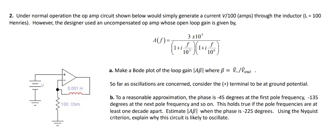
2. Under normal operation the op amp circuit shown below would simply generate a current V/100 (amps) through the inductor (L = 100 Henries). However, the designer used an uncompensated op amp whose open loop gain is given by, 3 x10⁵ A (f ) = Itif 103 a. Make a Bode plot of the loop gain |AB | where B = V_/Vout . So far as oscillations are concerned, consider the (+) terminal to be at ground potential. 0.001 H b. To a reasonable approximation, the phase is -45 degrees at the first pole frequency, -135 100 Ohm degrees at the next pole frequency and so on. This holds true if the pole frequencies are at least one decade apart. Estimate |AB | when the phase is -225 degrees. Using the Nyquist criterion, explain why this circuit is likely to oscillate
Step by Step Solution
There are 3 Steps involved in it

Get step-by-step solutions from verified subject matter experts