

Question: Structure shown in the figure is in static equilibrium. The goal is to design the link BD . Constraints on the design choices are as
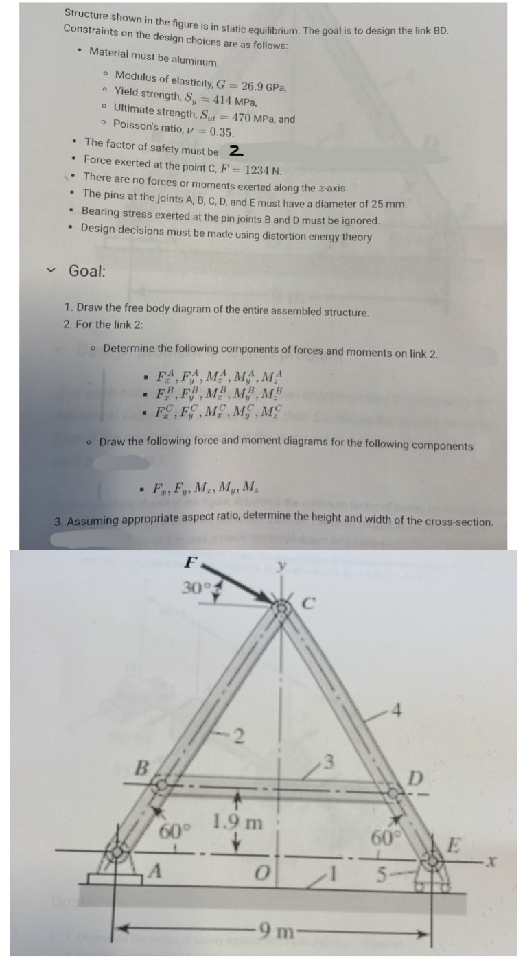
Structure shown in the figure is in static equilibrium. The goal is to design the link BD
Constraints on the design choices are as follows:
Material must be aluminum:
Modulus of elasticity, GPa,
Yield strength, MPa,
Ultimate strength, MPa, and
Poisson's ratio,
The factor of safety must be
Force exerted at the point C
There are no forces or moments exerted along the axis.
The pins at the joints and must have a diameter of mm
Bearing stress exerted at the pin joints B and D must be ignored.
Design decisions must be made using distortion energy theory
Goal:
Draw the free body diagram of the entire assembled structure.
For the link :
Determine the following components of forces and moments on link
Draw the following force and moment diagrams for the following components
Assuming appropriate aspect ratio, determine the height and width of the crosssection.
Step by Step Solution
There are 3 Steps involved in it
1 Expert Approved Answer
Step: 1 Unlock

Question Has Been Solved by an Expert!
Get step-by-step solutions from verified subject matter experts
Step: 2 Unlock
Step: 3 Unlock