

Question: Synchronous Sequential Logic: Gray Code Up/Down Counter A 3-bit Gray Code counts upward (from 0 to 7) using the following pattern: 000, 001, 011, 010,
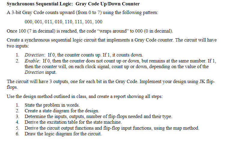
Synchronous Sequential Logic: Gray Code Up/Down Counter A 3-bit Gray Code counts upward (from 0 to 7) using the following pattern: 000, 001, 011, 010, 110, 111, 101, 100 Once 100 (7 in decimal) is reached, the code "wraps around" to 000 (0 in decimal) Create a synchronous sequential logic circuit that implements a Gray Code counter. The circuit will have two inputs 1. Direction: If 0, the counter counts up. If 1, it counts down. 2. Enable: If 0, then the counter does not count up or down, but remains at the same number. If 1, then the counter will, on each clock signal, count up or down, depending on the value of the Direction input. The circuit will have 3 outputs, one for each bit in the Gray Code. Implement your design using JK flip- flops Use the design method outlined in class, and create a report showing all steps 1. State the problem in words 2. Create a state diagram for the design. 3. Determine the inputs, outputs, number of flip-flops needed and their type 4. Derive the excitation table for the state machine 5. Derive the circuit output functions and flip-flop input functions, using the map method 6. Draw the logic diagram for the circuit. Synchronous Sequential Logic: Gray Code Up/Down Counter A 3-bit Gray Code counts upward (from 0 to 7) using the following pattern: 000, 001, 011, 010, 110, 111, 101, 100 Once 100 (7 in decimal) is reached, the code "wraps around" to 000 (0 in decimal) Create a synchronous sequential logic circuit that implements a Gray Code counter. The circuit will have two inputs 1. Direction: If 0, the counter counts up. If 1, it counts down. 2. Enable: If 0, then the counter does not count up or down, but remains at the same number. If 1, then the counter will, on each clock signal, count up or down, depending on the value of the Direction input. The circuit will have 3 outputs, one for each bit in the Gray Code. Implement your design using JK flip- flops Use the design method outlined in class, and create a report showing all steps 1. State the problem in words 2. Create a state diagram for the design. 3. Determine the inputs, outputs, number of flip-flops needed and their type 4. Derive the excitation table for the state machine 5. Derive the circuit output functions and flip-flop input functions, using the map method 6. Draw the logic diagram for the circuit
Step by Step Solution
There are 3 Steps involved in it

Get step-by-step solutions from verified subject matter experts