Question: System Description & State Diagram First task: Transform the following system description into a FSM state diagram (you can use any tool to create this
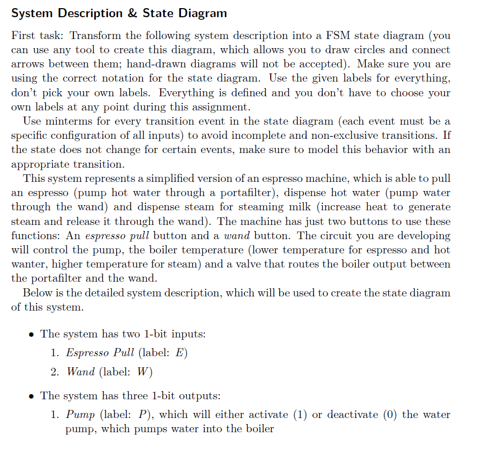
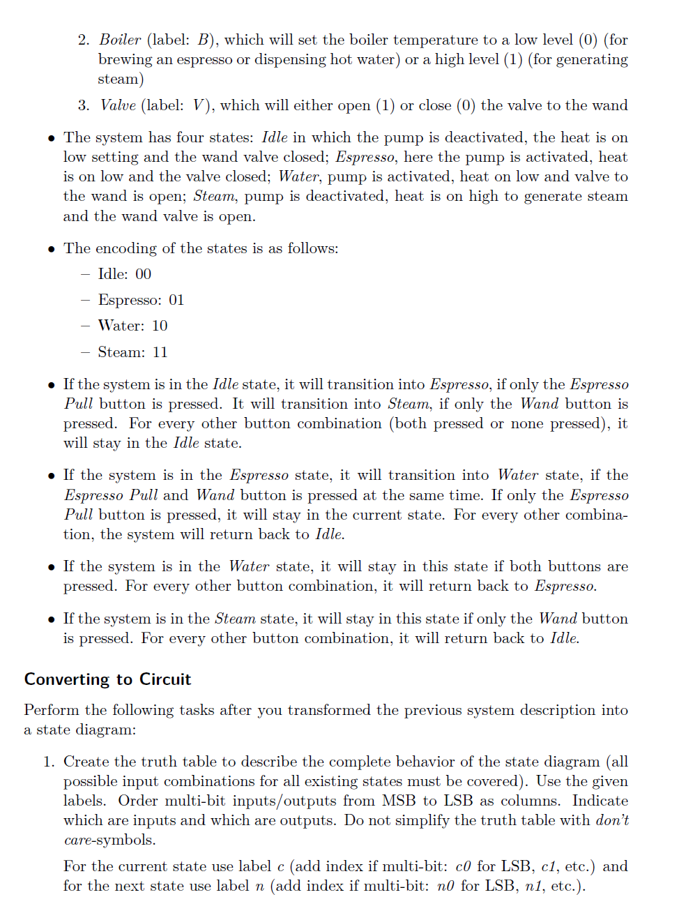
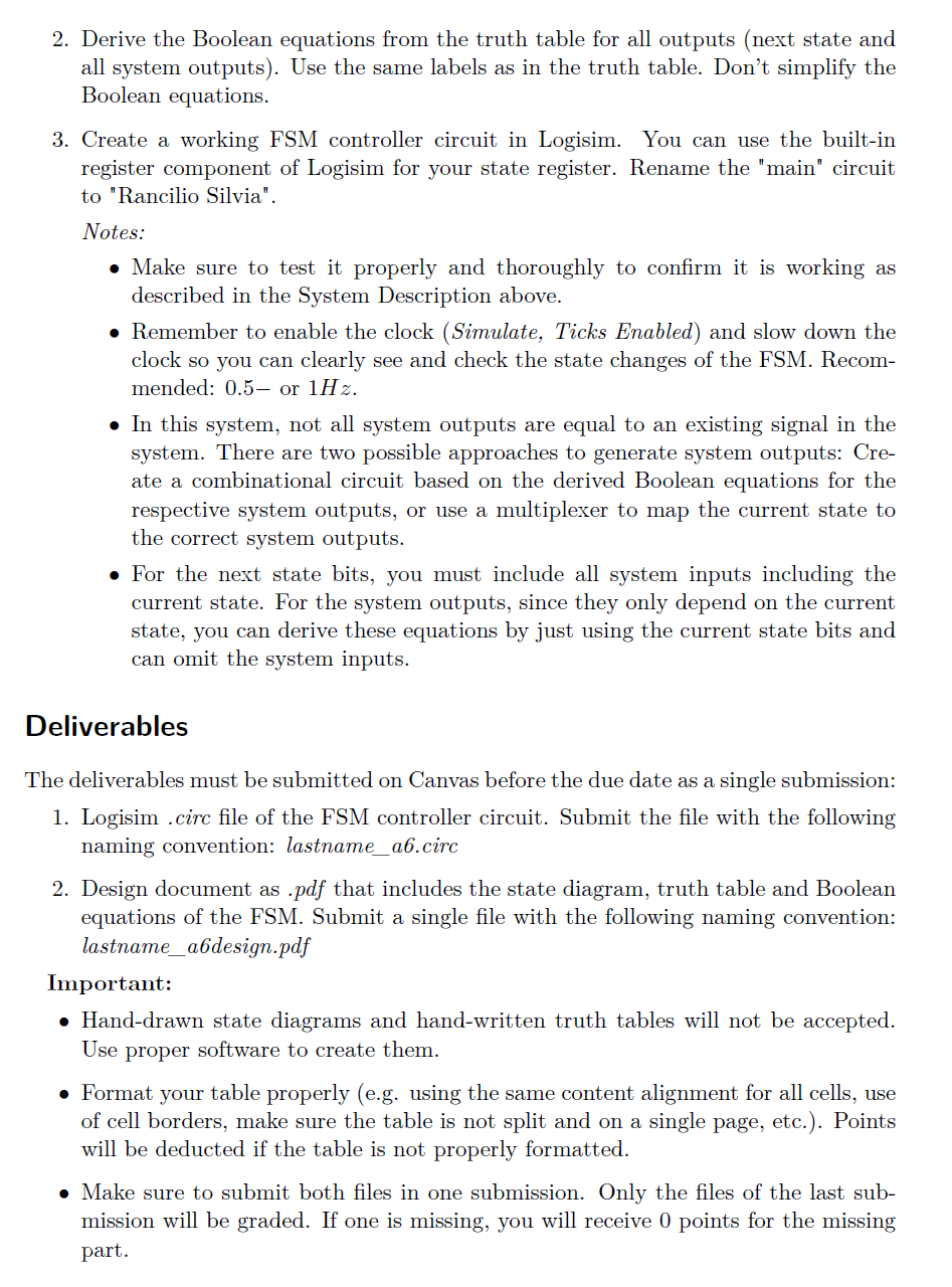
System Description & State Diagram First task: Transform the following system description into a FSM state diagram (you can use any tool to create this diagram, which allows you to draw circles and connect arrows between them; hand-drawn diagrams will not be accepted). Make sure you are using the correct notation for the state diagram. Use the given labels for everything, don't pick your own labels. Everything is defined and you don't have to choose your own labels at any point during this assignment. Use minterms for every transition event in the state diagram (each event must be a specific configuration of all inputs) to avoid incomplete and non-exclusive transitions. If the state does not change for certain events, make sure to model this behavior with an appropriate transition. This system represents a simplified version of an espresso machine, which is able to pull an espresso (pump hot water through a portafilter), dispense hot water (pump water through the wand) and dispense steam for steaming milk (increase heat to generate steam and release it through the wand). The machine has just two buttons to use these functions: An espresso pull button and a wand button. The circuit you are developing will control the pump, the boiler temperature (lower temperature for espresso and hot wanter, higher temperature for steam) and a valve that routes the boiler output between the portafilter and the wand. Below is the detailed system description, which will be used to create the state diagram of this system. e The system has two 1-bit inputs: 1. Espresso Pull (label: E) 2. Wand (label: W) e The system has three 1-bit outputs: 1. Pump (label: P), which will either activate (1) or deactivate (0) the water pump, which pumps water into the boiler 2. Boiler (label: B), which will set the boiler temperature to a low level (0) (for brewing an espresso or dispensing hot water) or a high level (1) (for generating steam) 3. Valve (label: V), which will either open (1) or close (0) the valve to the wand e The system has four states: Jdle in which the pump is deactivated, the heat is on low setting and the wand valve closed; Espresso, here the pump is activated, heat is on low and the valve closed; Water, pump is activated, heat on low and valve to the wand is open; Steam, pump is deactivated, heat is on high to generate steam and the wand valve is open. e The encoding of the states is as follows: Idle: 00 Espresso: O01 Water: 10 Steam: 11 e Ifthe system is in the /dle state, it will transition into E'spresso, if only the Espresso Pull button is pressed. It will transition into Steam, if only the Wand button is pressed. For every other button combination (both pressed or none pressed), it will stay in the Idle state. e If the system is in the Espresso state, it will transition into Water state, if the Espresso Pull and Wand button is pressed at the same time. If only the Espresso Pull button is pressed, it will stay in the current state. For every other combina- tion, the system will return back to Idle. e If the system is in the Water state, it will stay in this state if both buttons are pressed. For every other button combination, it will return back to Espresso. e Ifthe system is in the Steam state, it will stay in this state if only the Wand button is pressed. For every other button combination, it will return back to Idle. Converting to Circuit Perform the following tasks after you transformed the previous system description into a state diagram: 1. Create the truth table to describe the complete behavior of the state diagram (all possible input combinations for all existing states must be covered). Use the given labels. Order multi-bit inputs/outputs from MSB to LSB as columns. Indicate which are inputs and which are outputs. Do not simplify the truth table with don't care-symbols, For the current state use label (add index if multi-bit: c0 for LSB, c/, etc.) and for the next state use label n (add index if multi-bit: n0 for LSB, nJ, etc.). 2. Derive the Boolean equations from the truth table for all outputs (next state and all system outputs). Use the same labels as in the truth table. Don't simplify the Boolean equations. 3. Create a working FSM controller circuit in Logisim. You can use the built-in register component of Logisim for your state register. Rename the "main" circuit to "Rancilio Silvia". Notes: e Make sure to test it properly and thoroughly to confirm it is working as described in the System Description above. e Remember to enable the clock (Simulate, Ticks Enabled) and slow down the clock so you can clearly see and check the state changes of the FSM. Recom- mended: 0.5 or 1H2z. e In this system, not all system outputs are equal to an existing signal in the system. There are two possible approaches to generate system outputs: Cre- ate a combinational circuit based on the derived Boolean equations for the respective system outputs, or use a multiplexer to map the current state to the correct system outputs. e For the next state bits, you must include all system inputs including the current state. For the system outputs, since they only depend on the current state, you can derive these equations by just using the current state bits and can omit the system inputs. Deliverables The deliverables must be submitted on Canvas before the due date as a single submission: 1. Logisim .circ file of the FSM controller circuit. Submit the file with the following naming convention: lastname_a.cire 2. Design document as .pdf that includes the state diagram, truth table and Boolean equations of the FSM. Submit a single file with the following naming convention: lastname_ab6design.pdf Important: e Hand-drawn state diagrams and hand-written truth tables will not be accepted. Use proper software to create them. e Format your table properly (e.g. using the same content alignment for all cells, use of cell borders, make sure the table is not split and on a single page, etc.). Points will be deducted if the table is not properly formatted. e Make sure to submit both files in one submission. Only the files of the last sub- mission will be graded. If one is missing, you will receive 0 points for the missing part
Step by Step Solution
There are 3 Steps involved in it
1 Expert Approved Answer
Step: 1 Unlock
Question Has Been Solved by an Expert!
Get step-by-step solutions from verified subject matter experts
Step: 2 Unlock
Step: 3 Unlock
Students Have Also Explored These Related Accounting Questions!