

Question: system modelling Draw a complete bond graph of an electric hydraulic lift system below. Given that B1, B2 are friction constants of bearings
system modelling
Draw a complete bond graph of an electric hydraulic lift system below. Given that • B1, B2 are friction constants of bearings • K is twisting constant of the rotating rod • N1 : N2 is tooth ratio of the rack and pinion system • M is a motor and J is an inertia of rotating disk attached to the motor • The rack and pinion system pushes the Piston 1 to lift objects attached to Piston 2 • R1 and R2 are fluid resistance values of the lift • The hydraulic setup actually include a transformer element in it 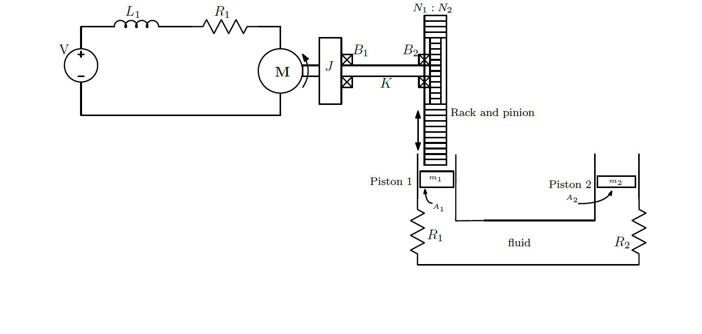
L1 R1 N1 : N2 B2 Rack and pinion Piston 1 Piston 2 A2 A1 R1 R2 fluid
Step by Step Solution
3.40 Rating (144 Votes )
There are 3 Steps involved in it
To create a bond graph for the electric hydraulic lift system follow these steps considering each component and interaction described Steps to Draw th... View full answer

Get step-by-step solutions from verified subject matter experts