

Question: System parameters are: Consider the given el The motor is a Permanent magnet DC motor. The output of the motor is connected to a gear
System parameters are:
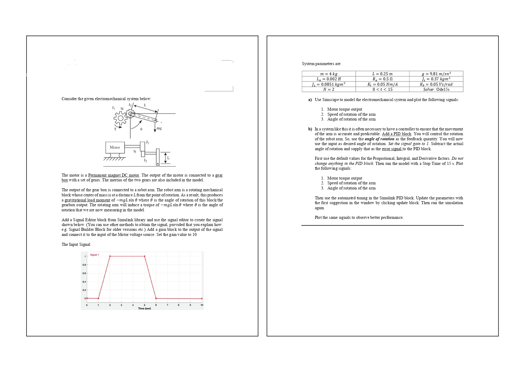
Consider the given el
The motor is a Permanent magnet DC motor. The output of the motor is connected to a gear box with a set of gears. The inertias of the two gears are also included in the model.
The output of the gear box is connected to a robot arm. The robot arm is a rotating mechanical block whose center of mass is at a distance L from the point of rotation. As a result, this produces a gravitational load moment of m g L sin theta where theta is the angle of rotation of this blockthe gearbox output. The rotating arm will induce a torque of m g L sin theta where theta is the angle of rotation that we are now measuring in the model.
Add a Signal Editor block from Simulink library and use the signal editor to create the signal shown below. You can use other methods to obtain the signal, provided that you explain how. eg Signal Builder Block for older versions etc. Add a gain block to the output of the signal and connect it to the input of the Motor voltage source. Set the gain value to
The Input Signal:
a Use Simscape to model the electromechanical system and plot the following signals:
Motor torque output
Speed of rotation of the arm
Angle of rotation of the arm
b In a system like this it is often necessary to have a controller to ensure that the movement of the arm is accurate and predictable. Add a PID block. You will control the rotation of the robot arm. So use the angle of rotation as the feedback quantity. You will now use the input as desired angle of rotation. Set the signal gain to Subtract the actual angle of rotation and supply that as the error signal to the PID block.
First use the default values for the Proportional, Integral, and Derivative factors. Do not change anything in the PID block. Then run the model with a Stop Time of s Plot the following signals:
Motor torque output
Speed of rotation of the arm
Angle of rotation of the arm
Then use the automated tuning in the Simulink PID block. Update the parameters with the first suggestion in the window by clicking update block. Then run the simulation again.
Plot the same signals to observe better performance.
Step by Step Solution
There are 3 Steps involved in it
1 Expert Approved Answer
Step: 1 Unlock

Question Has Been Solved by an Expert!
Get step-by-step solutions from verified subject matter experts
Step: 2 Unlock
Step: 3 Unlock