

Question: Table 1 (Used in first question): PROCESS PARAMETERS R R Sheet Resistance 1523.7 Contact Resistance Gate Oxide Thickness N+ 6.2 7.2 + P+PLY POLY N+BLK
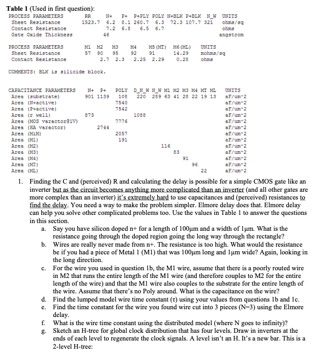
Table 1 (Used in first question): PROCESS PARAMETERS R R Sheet Resistance 1523.7 Contact Resistance Gate Oxide Thickness N+ 6.2 7.2 + P+PLY POLY N+BLK P+BLK N_W 8.1 260.7 6.3 72.3 107.7 321 6.8 6.5 6.7 UNITS ohms/s9 ohms angstrom PROCESS PARAMETERS Sheet Resistance Contact Resistance M1 M2 M3 57 90 95 2.7 2.3 M4 M5 (MT) M6 (ML) 92 91 14.29 2.25 2.29 0.28 UNITS mohms/ag ohms COMMENTS: BLK is silicide block. N+ B+ POLY 901 1139108 7540 7542 D_N_N N N M M2 M3 M4 MI ML 220 289 63 41 28 22 19 13 873 1088 7776 CAPACITACE PARAMETERS Area (substrate) Area (N-active) Area (P-active) Area (well) Area (MOS varactor@iv) Area (HA varactor) Area (MM) Area (M1) Area (M2) Area (M3) Area (M4) Area (MT) Area (ML) 2744 2057 191 UNITS F/m2 a/m2 aF/m2 a/m2 aF/m2 aF/m2 aF/m2 aF/m2 aF/m2 af/um 2 a/m2 a / 2 a/m2 116 22 1. Finding the Cand (perceived) R and calculating the delay is possible for a simple CMOS gate like an inverter but as the circuit becomes anything more complicated than an inverter (and all other gates are more complex than an inverter) it's extremely hard to use capacitances and perceived) resistances to find the delay. You need a way to make the problem simpler. Elmore delay does that. Elmore delay can help you solve other complicated problems too. Use the values in Table 1 to answer the questions in this section. a. Say you have silicon doped n+ for a length of 100um and a width of lum. What is the resistance going through the doped region going the long way through the rectangle? b. Wires are really never made from nt. The resistance is too high. What would the resistance be if you had a piece of Metal 1 (MI) that was 100 m long and lum wide? Again, looking in the long direction. c. For the wire you used in question lb, the Ml wire, assume that there is a poorly routed wire in M2 that runs the entire length of the Ml wire and therefore couples to M2 for the entire length of the wire) and that the Ml wire also couples to the substrate for the entire length of the wire. Assume that there's no Poly around. What is the capacitance on the wire? d. Find the lumped model wire time constant (t) using your values from questions lb and lc. e. Find the time constant for the wire you found wire cut into 3 pieces (N=3) using the Elmore delay. f. What is the wire time constant using the distributed model (where N goes to infinity)? g. Sketch an H-tree for global clock distribution that has four levels. Draw in inverters at the ends of each level to regenerate the clock signals. A level isn't an H. It's a new bar. This is a 2-level H-tree: Table 1 (Used in first question): PROCESS PARAMETERS R R Sheet Resistance 1523.7 Contact Resistance Gate Oxide Thickness N+ 6.2 7.2 + P+PLY POLY N+BLK P+BLK N_W 8.1 260.7 6.3 72.3 107.7 321 6.8 6.5 6.7 UNITS ohms/s9 ohms angstrom PROCESS PARAMETERS Sheet Resistance Contact Resistance M1 M2 M3 57 90 95 2.7 2.3 M4 M5 (MT) M6 (ML) 92 91 14.29 2.25 2.29 0.28 UNITS mohms/ag ohms COMMENTS: BLK is silicide block. N+ B+ POLY 901 1139108 7540 7542 D_N_N N N M M2 M3 M4 MI ML 220 289 63 41 28 22 19 13 873 1088 7776 CAPACITACE PARAMETERS Area (substrate) Area (N-active) Area (P-active) Area (well) Area (MOS varactor@iv) Area (HA varactor) Area (MM) Area (M1) Area (M2) Area (M3) Area (M4) Area (MT) Area (ML) 2744 2057 191 UNITS F/m2 a/m2 aF/m2 a/m2 aF/m2 aF/m2 aF/m2 aF/m2 aF/m2 af/um 2 a/m2 a / 2 a/m2 116 22 1. Finding the Cand (perceived) R and calculating the delay is possible for a simple CMOS gate like an inverter but as the circuit becomes anything more complicated than an inverter (and all other gates are more complex than an inverter) it's extremely hard to use capacitances and perceived) resistances to find the delay. You need a way to make the problem simpler. Elmore delay does that. Elmore delay can help you solve other complicated problems too. Use the values in Table 1 to answer the questions in this section. a. Say you have silicon doped n+ for a length of 100um and a width of lum. What is the resistance going through the doped region going the long way through the rectangle? b. Wires are really never made from nt. The resistance is too high. What would the resistance be if you had a piece of Metal 1 (MI) that was 100 m long and lum wide? Again, looking in the long direction. c. For the wire you used in question lb, the Ml wire, assume that there is a poorly routed wire in M2 that runs the entire length of the Ml wire and therefore couples to M2 for the entire length of the wire) and that the Ml wire also couples to the substrate for the entire length of the wire. Assume that there's no Poly around. What is the capacitance on the wire? d. Find the lumped model wire time constant (t) using your values from questions lb and lc. e. Find the time constant for the wire you found wire cut into 3 pieces (N=3) using the Elmore delay. f. What is the wire time constant using the distributed model (where N goes to infinity)? g. Sketch an H-tree for global clock distribution that has four levels. Draw in inverters at the ends of each level to regenerate the clock signals. A level isn't an H. It's a new bar. This is a 2-level H-tree
Step by Step Solution
There are 3 Steps involved in it

Get step-by-step solutions from verified subject matter experts