

Question: Table P4 Inputs Outputs Present State Next State QI 00 PIPO CTL TS ST HIHO FIFO 0 X X HG HG 0 00 10 X
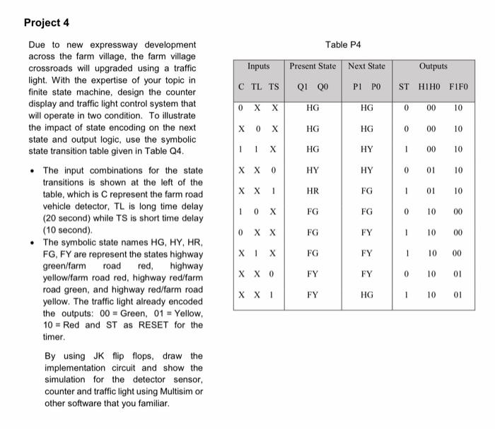
Table P4 Inputs Outputs Present State Next State QI 00 PIPO CTL TS ST HIHO FIFO 0 X X HG HG 0 00 10 X 0 x HG HG 0 00 10 X HG HY 1 00 10 X X 0 HY HY 0 01 10 X X 1 HR FG 1 01 10 Project 4 Due to new expressway development across the farm village, the farm village crossroads will upgraded using a traffic light. With the expertise of your topic in finite state machine, design the counter display and traffic light control system that will operate in two condition. To illustrate the impact of state encoding on the next state and output logic, use the symbolic state transition table given in Table Q4. The input combinations for the state transitions is shown at the left of the table, which is represent the farm road vehicle detector, TL is long time delay (20 second) while TS is short time delay (10 second). The symbolic state names HG, HY, HR, FG, FY are represent the states highway green/farm road red, highway yellow/farm road red, highway red/farm road green, and highway red/farm road yellow. The traffic light already encoded the outputs: 00 = Green, 01 = Yellow, 10 = Red and ST as RESET for the timer. By using JK flip flops, draw the implementation circuit and show the simulation for the detector sensor, counter and traffic light using Multisim or other software that you familiar. 10 X FG FG 0 10 00 0 X X FG FY 1 10 00 X 1 FG FY 1 10 00 X X 0 FY FY 0 10 01 X X 1 FY HG 1 10 01
Step by Step Solution
There are 3 Steps involved in it

Get step-by-step solutions from verified subject matter experts