

Question: table [ [ TABLE P 7 - 2 , Data for Problems 7 - 5 to 7 - 6 and 7 - 5 8
tableTABLE PData for Problems to and RowLink Link Offset,theta omega alpha abcdefg
FIGURE P
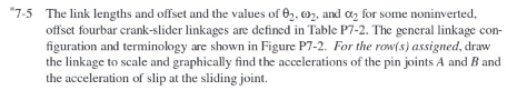
Configuration and terminology for Problems to and to The link lengths and offset and the values of and for some noninverted,
offset fourbar crankslider linkages are defined in Table P The general linkage con
figuration and terminology are shown in Figure P For the rows assigned, draw
the linkage to scale and graphically find the accelerations of the pin joints A and and
the acceleration of slip at the sliding joint.
use row a in the picture for values
Step by Step Solution
There are 3 Steps involved in it
1 Expert Approved Answer
Step: 1 Unlock

Question Has Been Solved by an Expert!
Get step-by-step solutions from verified subject matter experts
Step: 2 Unlock
Step: 3 Unlock