

Question: Task 1 : Building the full device For the lab assignment you will connect the four stages with the values that you obtained in the
Task : Building the full device
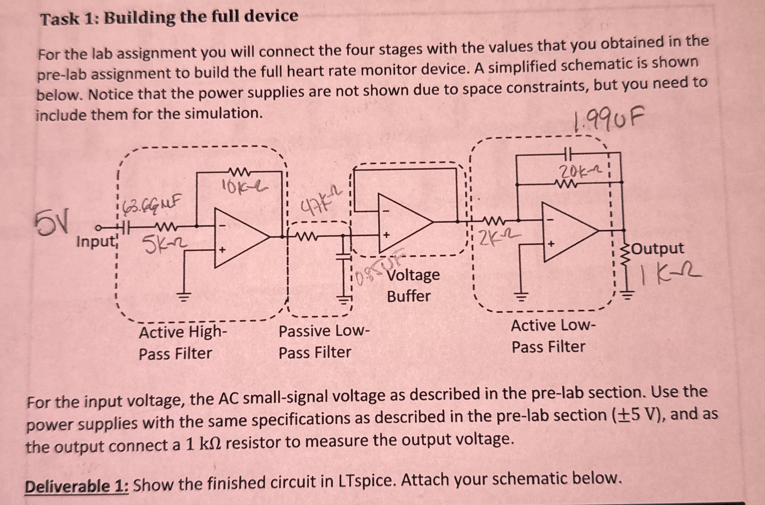
For the lab assignment you will connect the four stages with the values that you obtained in the prelab assignment to build the full heart rate monitor device. A simplified schematic is shown below. Notice that the power supplies are not shown due to space constraints, but you need to include them for the simulation.
For the input voltage, the smallsignal voltage as described in the prelab section. Use the power supplies with the same specifications as described in the prelab section and as the output connect a resistor to measure the output voltage.
Deliverable :
What can it be concluded about the role of the lowpass filter in stage TWO and the voltage buffer i stage for the heart rate monitor?
What can it be concluded about the role of the active lowpass filter in stage FOUR for the heart rate monitor?
Based on the frequency response plot of the full device, which range frequencies are amplified? Do these frequencies correspond to the avarage heart rate frequency?
which changes or improvements would it help this fourstage filter to work better at amplifying the heart rate frequencies while minimizing noise?
Step by Step Solution
There are 3 Steps involved in it
1 Expert Approved Answer
Step: 1 Unlock

Question Has Been Solved by an Expert!
Get step-by-step solutions from verified subject matter experts
Step: 2 Unlock
Step: 3 Unlock