

Question: Task 3: 4 options Now your task is to combine what you did in Tasks 1 and 2 to build a circuit that has four
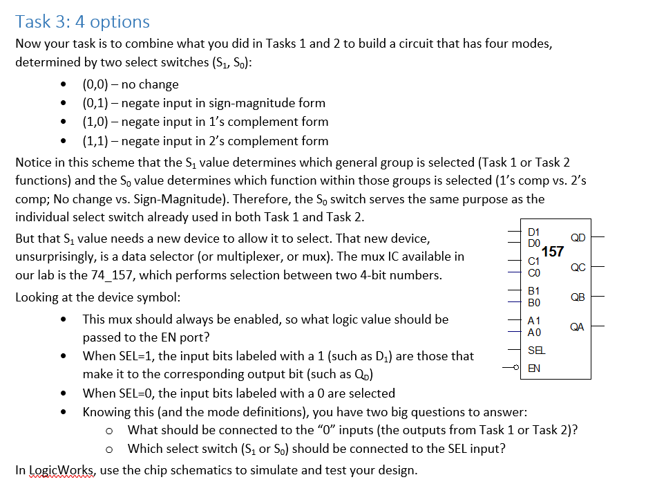
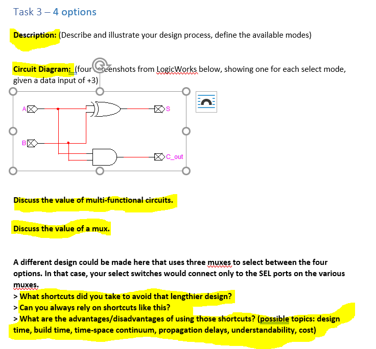
Task 3: 4 options Now your task is to combine what you did in Tasks 1 and 2 to build a circuit that has four modes, determined by two select switches (S1,S0) : - (0,0) - no change - (0,1) - negate input in sign-magnitude form - (1,0) - negate input in 1's complement form - (1,1) - negate input in 2's complement form Notice in this scheme that the S1 value determines which general group is selected (Task 1 or Task 2 functions) and the S0 value determines which function within those groups is selected (1's comp vs. 2's comp; No change vs. Sign-Magnitude). Therefore, the S0 switch serves the same purpose as the individual select switch already used in both Task 1 and Task 2. But that S1 value needs a new device to allow it to select. That new device, unsurprisingly, is a data selector (or multiplexer, or mux). The mux IC available in our lab is the 74_157, which performs selection between two 4-bit numbers. Looking at the device symbol: - This mux should always be enabled, so what logic value should be passed to the EN port? - When SEL=1, the input bits labeled with a 1 (such as D1 ) are those that make it to the corresponding output bit (such as Q0 ) - When SEL=0, the input bits labeled with a 0 are selected - Knowing this (and the mode definitions), you have two big questions to answer: - What should be connected to the "0" inputs (the outputs from Task 1 or Task 2)? - Which select switch (S1 or S0) should be connected to the SEL input? In LogicWorks, use the chip schematics to simulate and test your design. Description: (Describe and illustrate your design process, define the available modes) Circuit Diagram: (four Geenshots from LogicWorks below, showing one for each select mode, given a data input of +3 ) Discuss the value of multi-functional circuits. Discuss the value of a mux. A different design could be made here that uses three muxes to select between the four options. In that case, your select switches would connect only to the SEL ports on the various muxes. > What shortcuts did you take to avoid that lengthier design? > Can you always rely on shortcuts like this? > What are the advantages/disadvantages of using those shortcuts? (possible topics: design time, build time, time-space continuum, propagation delays, understandability, cost)
Step by Step Solution
There are 3 Steps involved in it

Get step-by-step solutions from verified subject matter experts