

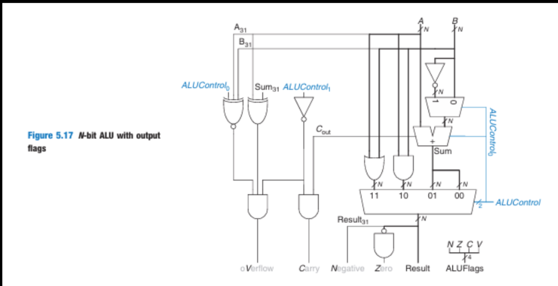
Question: Task: Construct a 4 - bit Arithmetic Logic Unit ( ALU ) as depicted in Figure 5 . 1 7 from your textbook, using Logisim
Task: Construct a bit Arithmetic Logic Unit ALU as depicted in Figure from your textbook, using Logisim and any gates, except for specific restrictions noted below.
Components:
Inputs and Outputs: Incorporate dip switches for the inputs and LEDs for outputs, including the carry, to facilitate testing.
Specifications:
Adder Construction:
Do not use the prebuilt adder from Logisims arithmetic section.
Utilize your bit full adder from Problem as a subcircuit.
Manually connect these bit adders to form a bit adder. Ensure all connections and the routing from the bit input bus to each adder are clearly visible.
Employ splitters for the inputs and outputs of your adder to correctly route the bus inputs to each bit.
Logic Gates:
You may use multibit gates for logic functions.
Use a bit multiplexer for selecting output, but not for inversion in subtraction operations.
Implement the controlled inversion for subtraction using an XOR gate as discussed in class.
Follow the overflow logic as taught in class, not as per the textbooks method.
Documentation and Image Requirements:
Provide a detailed schematic of the entire bit ALU setup.
Include a single comprehensive image showing the ALU performing each of the four operations with input values and formatted in two's complement Ensure this image captures the entire circuit setup including dip switches and LEDs.
Figure bit ALU with output flags
Step by Step Solution
There are 3 Steps involved in it
1 Expert Approved Answer
Step: 1 Unlock

Question Has Been Solved by an Expert!
Get step-by-step solutions from verified subject matter experts
Step: 2 Unlock
Step: 3 Unlock