

Question: Task: Part 1 : Beam analysis The timber beam in Figure 1 is simply supported at points A and E . The cross - section
Task:
Part : Beam analysis
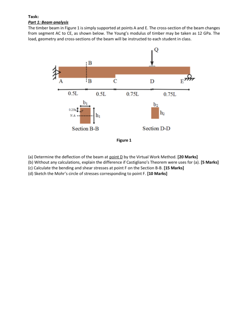
The timber beam in Figure is simply supported at points A and E The crosssection of the beam changes from segment AC to CE as shown below. The Young's modulus of timber may be taken as GPa The load, geometry and crosssections of the beam will be instructed to each student in class.
a Determine the deflection of the beam at point D by the Virtual Work Method. Marks
b Without any calculations, explain the difference if Castigliano's Theorem were uses for a Marks
c Calculate the bending and shear stresses at point F on the Section BB Marks
d Sketch the Mohr's circle of stresses corresponding to point F Marks
where;
Load Q kn
Length L m
Crosssection dimensions:
b mm
h mm
b mm
h mm
Step by Step Solution
There are 3 Steps involved in it
1 Expert Approved Answer
Step: 1 Unlock

Question Has Been Solved by an Expert!
Get step-by-step solutions from verified subject matter experts
Step: 2 Unlock
Step: 3 Unlock