

Question: Task: Your task is to program the code for The Black Box. You have been given a template code file into which your code will
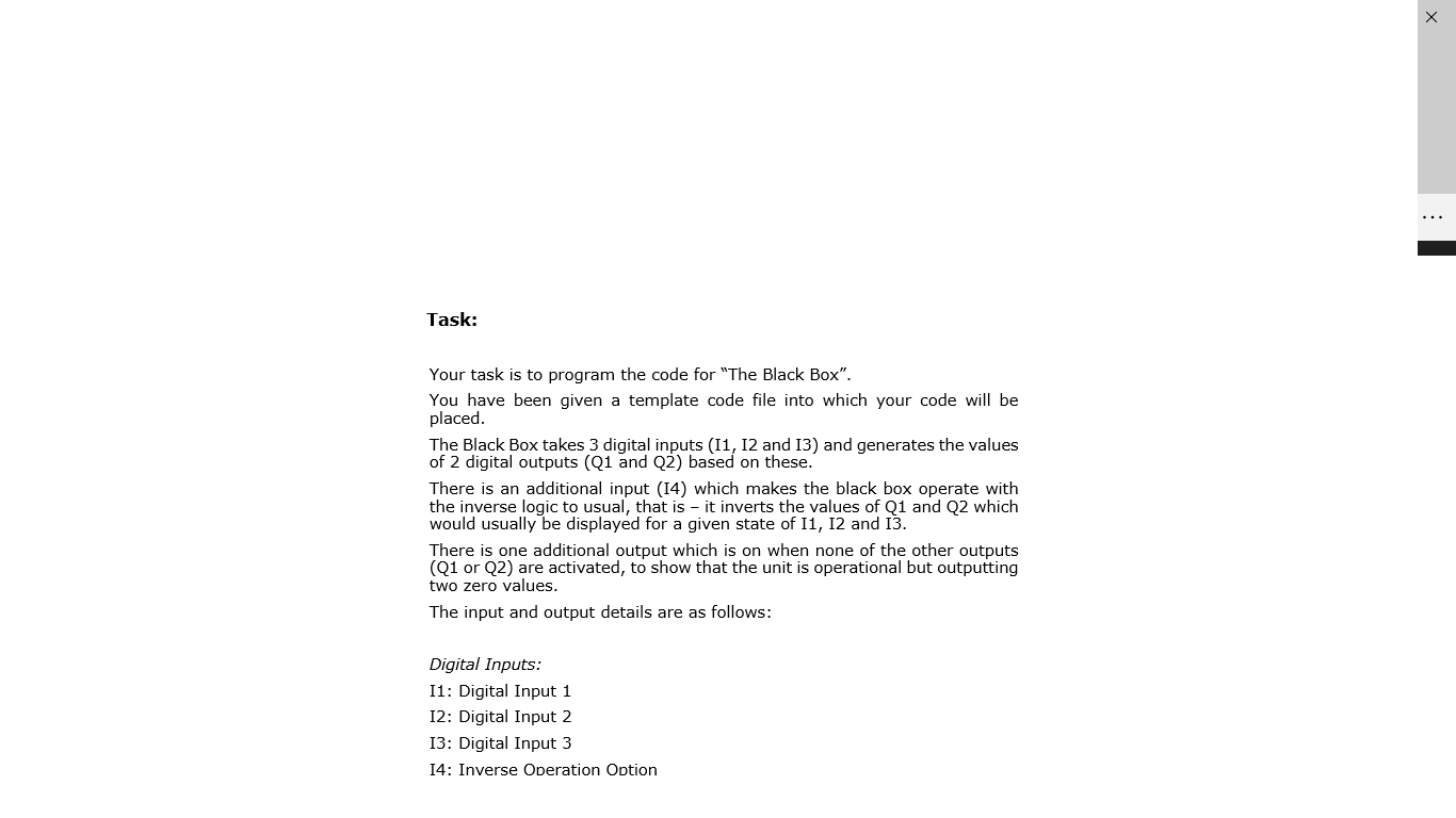
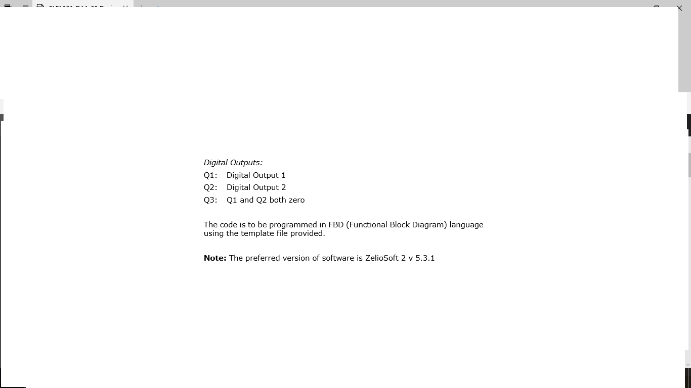
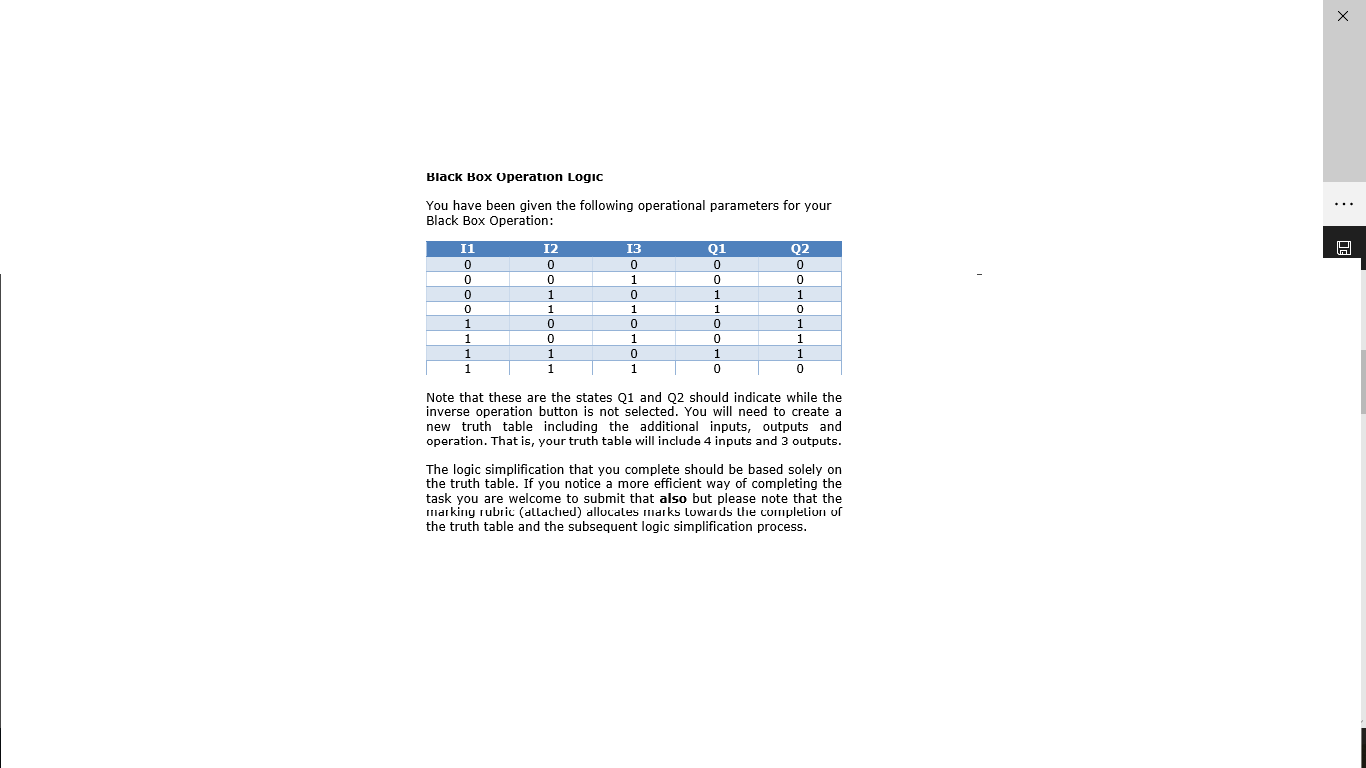
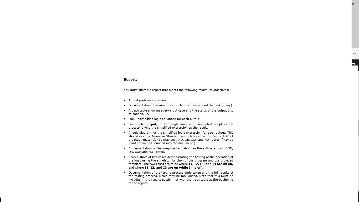
Task: Your task is to program the code for "The Black Box". You have been given a template code file into which your code will be placed. The Black Box takes 3 digital inputs (11, 12 and 13) and generates the values of 2 digital outputs (Q1 and Q2) based on these. There is an additional input (14) which makes the black box operate with the inverse logic to usual, that is - it inverts the values of Q1 and Q2 which would usually be displayed for a given state of 11, 12 and 13. There is one additional output which is on when none of the other outputs (Q1 or Q2) are activated, to show that the unit is operational but outputting two zero values. The input and output details are as follows: Digital Inputs: 11: Digital Input 1 12: Digital Input 2 13: Digital Input 3 14: Inverse Operation Option Digital Outputs: Q1: Digital Output 1 Q2: Digital Output 2 Q3: Q1 and Q2 both zero The code is to be programmed in FBD (Functional Block Diagram) language using the template file provided. Note: The preferred version of software is ZelioSoft 2 v 5.3.1 Black Box Operation Logic You have been given the following operational parameters for your Black Box Operation: A Q1 0 0 11 0 0 0 0 1 1 1 1 12 0 0 1 1 0 0 1 1 0 1 0 1 0 1 0 1 0 0 1 0 Q2 0 0 1 0 1 1 1 0 1 Note that these are the states Q1 and 22 should indicate while the inverse operation button is not selected. You will need to create a new truth table including the additional inputs, outputs and operation. That is, your truth table will include 4 inputs and 3 outputs. The logic simplification that you complete should be based solely on the truth table. If you notice a more efficient way of completing the task you are welcome to submit that also but please note that the markiny rubric (allached) allocales marks Lowards the completion of the truth table and the subsequent logic simplification process. Report: You must submit a report that meets the following minimum objectives: A brief problem statement. Documentation of assumptions or clarifications around the task (if any). A truth table showing every input case and the status of the output bits at each value. Full, unsimplified logic equations for each output. For each output, a Karnaugh map and completed simplification process, giving the simplified expression as the result. A logic diagram for the simplified logic expression for each output. This should use the American Standard symbols as shown in Figure 4.26 of the study material. You may use AND, OR, XOR and NOT gates. (May be hand drawn and scanned into the document.) Implementation of the simplified equations in the software using AND, OR, XOR and NOT gates. Screen shots of two cases demonstrating the testing of the operation of the logic using the simulator function of the program and the provided template. The two cases are to be where 11, 12, 13, and 14 are all on, and where 11, 12, and 13 are on while 14 is off. Documentation of the testing process undertaken and the full results of the testing process, which may be tabularised. Note that this must be included in the results section not with the truth table at the beginning of the report. Task: Your task is to program the code for "The Black Box". You have been given a template code file into which your code will be placed. The Black Box takes 3 digital inputs (11, 12 and 13) and generates the values of 2 digital outputs (Q1 and Q2) based on these. There is an additional input (14) which makes the black box operate with the inverse logic to usual, that is - it inverts the values of Q1 and Q2 which would usually be displayed for a given state of 11, 12 and 13. There is one additional output which is on when none of the other outputs (Q1 or Q2) are activated, to show that the unit is operational but outputting two zero values. The input and output details are as follows: Digital Inputs: 11: Digital Input 1 12: Digital Input 2 13: Digital Input 3 14: Inverse Operation Option Digital Outputs: Q1: Digital Output 1 Q2: Digital Output 2 Q3: Q1 and Q2 both zero The code is to be programmed in FBD (Functional Block Diagram) language using the template file provided. Note: The preferred version of software is ZelioSoft 2 v 5.3.1 Black Box Operation Logic You have been given the following operational parameters for your Black Box Operation: A Q1 0 0 11 0 0 0 0 1 1 1 1 12 0 0 1 1 0 0 1 1 0 1 0 1 0 1 0 1 0 0 1 0 Q2 0 0 1 0 1 1 1 0 1 Note that these are the states Q1 and 22 should indicate while the inverse operation button is not selected. You will need to create a new truth table including the additional inputs, outputs and operation. That is, your truth table will include 4 inputs and 3 outputs. The logic simplification that you complete should be based solely on the truth table. If you notice a more efficient way of completing the task you are welcome to submit that also but please note that the markiny rubric (allached) allocales marks Lowards the completion of the truth table and the subsequent logic simplification process. Report: You must submit a report that meets the following minimum objectives: A brief problem statement. Documentation of assumptions or clarifications around the task (if any). A truth table showing every input case and the status of the output bits at each value. Full, unsimplified logic equations for each output. For each output, a Karnaugh map and completed simplification process, giving the simplified expression as the result. A logic diagram for the simplified logic expression for each output. This should use the American Standard symbols as shown in Figure 4.26 of the study material. You may use AND, OR, XOR and NOT gates. (May be hand drawn and scanned into the document.) Implementation of the simplified equations in the software using AND, OR, XOR and NOT gates. Screen shots of two cases demonstrating the testing of the operation of the logic using the simulator function of the program and the provided template. The two cases are to be where 11, 12, 13, and 14 are all on, and where 11, 12, and 13 are on while 14 is off. Documentation of the testing process undertaken and the full results of the testing process, which may be tabularised. Note that this must be included in the results section not with the truth table at the beginning of the report
Step by Step Solution
There are 3 Steps involved in it

Get step-by-step solutions from verified subject matter experts