

Question: 1. Using the schematic capture software construct a full adder as designed in the PRE-LAB. Simulate the circuit to make sure that it is
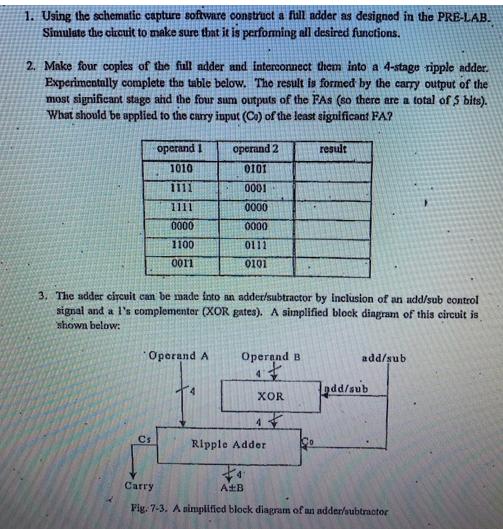
1. Using the schematic capture software construct a full adder as designed in the PRE-LAB. Simulate the circuit to make sure that it is performing all desired functions. 2. Make four copies of the full adder and interconnect them into a 4-stage ripple adder. Experimentally complete the table below. The result is formed by the carry output of the most significant stage and the four sum outputs of the FAS (so there are a total of 5 bits). What should be applied to the carry input (Co) of the least significant FA? operand 1 1010 1111 1111 0000 1100 0011 Operand A Cs 3. The adder circuit can be made into an adder/subtractor by inclusion of an add/sub control signal and a l's complementer (XOR gates). A simplified block diagram of this circuit is shown below: operand 2 0101 0001 0000 0000 0111 0101 4 Operand B 4 Ripple Adder 4 XOR result A+B add/sub add/sub Carry Fig. 7-3. A simplified block diagram of an adder/subtractor
Step by Step Solution
3.42 Rating (158 Votes )
There are 3 Steps involved in it
Answer simulation results the simualtion re... View full answer

Get step-by-step solutions from verified subject matter experts