

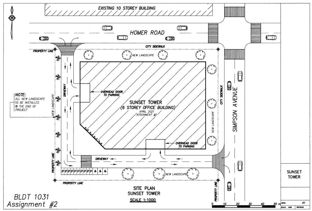
The attached sketch shows the proposed site and the location of the building footprint. The structure is
Question:
The attached sketch shows the proposed site and the location of the building footprint.
The structure is comprised of a combination of cast-in-place concrete and structural steel construction. The main walls and floor slab are reinforced concrete with the balance of the structure comprised of structural steel and metal decking. All decking will be covered with a concrete topping. All interior walls are steel stud framing with drywall finishes.
The North and East sides of the facility are in relatively close proximity to existing roads and sidewalks that must remain functional. The excavation will be approximately 25 feet in depth.
During your concrete pour, you intend to use a boom pump whenever possible but the majority of your planning will be done with the tower crane using a 1 1⁄2 yard concrete bucket. The bucket weighs 6,000 pounds when fully loaded. In late stages of construction, various sub-contractors also require use of the crane for loading and moving materials around the site. You plan to mobilize a tower crane (only one tower crane) with a L4 jib and a two-part line.
The general conditions and nature of the job requires you to mobilize the following items:
A temporary field office (10’ x 40’)
First aid facility and meeting room (10’ x 40’)
Owner designated field office (10’ x 40’)
Storage compound (25’ x 30’)
Four site offices for major sub-contractors (each 10’ x 40’)
Instructions
Prepare a plan showing the construction site layout.
Indicate all the necessary temporary requirements and provisions you may need including, but not limited to, the following:
• Temporary site officesLocation of the tower crane (one only) & indicate reach at 6,000 lb
Main access and intended traffic control
Hoarding and protection
Shoring
- • Any other necessary temporary facilities you can think of3. Layout your plan on a piece of 8 1/2” x 11” paper at a scale of 1:750 (or you can plot this using any computer software you like but it must be to a scale of 1:750).You can get the dimensions for the site and footprint of the building by using a metric scale measuring from the attached plan, which is drawn at a scale of 1:1000
4. Use the data in the Crane Reach Table to determine the maximum reach of the crane at 6,000 lb and show the maximum reach on your site layout.
Hint: You can use the method of interpolation to determine the maximum reach of the crane from the values in the table. In another word, you can assume Hook Reach and Lifting Capacities are in a linear relationship!
3. Layout your plan on a piece of 8 1/2” x 11” paper at a scale of 1:750 (or you can plot this using any computer software you like but it must be to a scale of 1:750).
You can get the dimensions for the site and footprint of the building by using a metric scale measuring from the attached plan, which is drawn at a scale of 1:1000
4. Use the data in the Crane Reach Table to determine the maximum reach of the crane at 6,000 lb and show the maximum reach on your site layout.
You can use the method of interpolation to determine the maximum reach of the crane from the values in the table. In another word, you can assume Hook Reach and Lifting Capacities are in a linear relationship!
Expert Answer:
Here is the construction site layout Construction site layout The following temporary requirements a... View the full answer


Vector Mechanics for Engineers Statics and Dynamics
ISBN: 978-0073212227
8th Edition
Authors: Ferdinand Beer, E. Russell Johnston, Jr., Elliot Eisenberg, William Clausen, David Mazurek, Phillip Cornwell
