

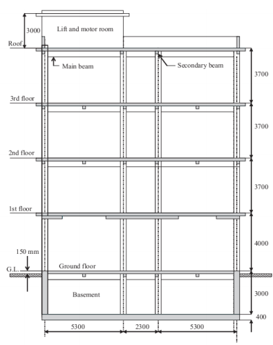
Question: The building shown in the figures below, is a 3 - bay multi - storeyed reinforced concrete framed structure consisting of two external bays of
The building shown in the figures below, is a bay multistoreyed reinforced concrete framed
structure consisting of two external bays of m span and an internal bay of m span. The
frames are spaced at m cc The length of the building is m The height of the building
is m comprising storey with the st floor m high from the ground floor to the firstfloor level and the next floors each m high. There is a provision for the basement. The
building also houses an elevator and also an emergency fire escape staircase at the back of the
building. The basic room size is m width and length with mm partition walls.Design Data
The following design data are to be assumed in the analyses and design of structure:
Number of bays
Number of stories
Number of frames
Spacing of frames m
Spacing of longitudinal beams m
Span of st bay from left m
Span of nd bay from left m
Span of rd bay from leftmHeight from ground floor to st floor m
Height from st floor to nd floor m
Height from nd floor to rd floor m
Height from rd floor to roof m
Bulk density of reinforced concrete, BS : Part :
kNm
Bulk density of reinforced Eurocode part kNm
Allowable bearing capacity of soil noncohesive at m depth after
geotechnical investigation BS : kNm
Density of soil, Eurocode : Part kNm
Live loads on roof with access Eurocode : Part kNm
Live loads on floors including ground floor Eurocode : Part
kNm
Basic wind speed velocity BS : Part : ms
mm ceiling finish kNm
mm insulating screed over slab at roof level and mm over other slabs
mm asphalt over roof screedkm
mm partition walls light weight aggregate concretekNm
mm plaster on both faces of walls mm deep slab
a Calculate the applied vertical loadings on all beams and frames. You must show
your structural framing in your solution.
b Determine design bending moments and shear forces in one typical main frame
AD and one typical one secondary beam on the rd floor. use eurocode in this design
Step by Step Solution
There are 3 Steps involved in it
1 Expert Approved Answer
Step: 1 Unlock

Question Has Been Solved by an Expert!
Get step-by-step solutions from verified subject matter experts
Step: 2 Unlock
Step: 3 Unlock