

The diagram below is a 4-bit Adder-Subtractor circuit. Given that the circuit has the input values shown
Fantastic news! We've Found the answer you've been seeking!
Question:
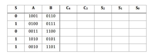
The diagram below is a 4-bit Adder-Subtractor circuit. Given that the circuit has the input values shown in the table below for S, Ai, and Bi, determine the outputs at S0, S1, S2, S3, and C4 for each input combination.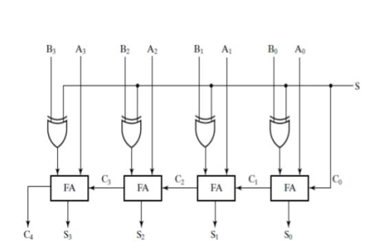
Complete the table below
Expert Answer:

Related Book For 

Posted Date:
