

Question: The elements in the Figure 2 are defined as follows: v1 = v 2 2 + v2 4i1 6 ve i2 = i1v2
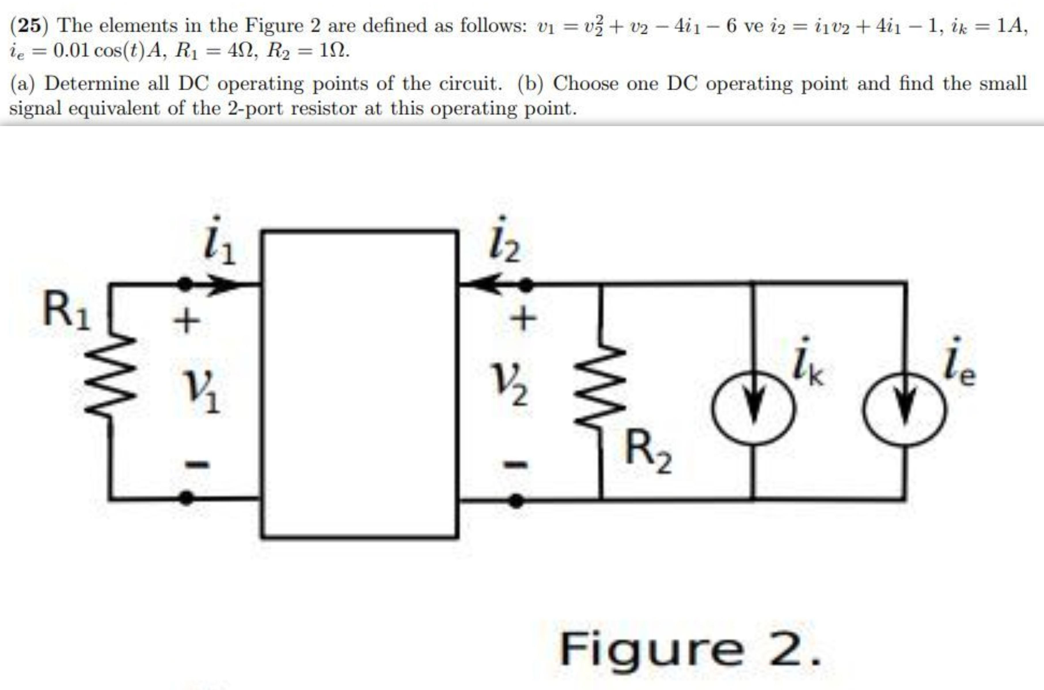
The elements in the Figure 2 are defined as follows: v1 = v 2 2 + v2 − 4i1 − 6 ve i2 = i1v2 + 4i1 − 1, ik = 1A, ie = 0.01 cos(t)A, R1 = 4Ω, R2 = 1Ω. (a) Determine all DC operating points of the circuit. (b) Choose one DC operating point and find the small signal equivalent of the 2-port resistor at this operating point.
(25) The elements in the Figure 2 are defined as follows: v1 = v + v2 - 4i1 6 ve i2 = i1v2 + 4i1 1, ik = 1A, ie = 0.01 cos(t)A, R1 = 42, R2 = 1N. (a) Determine all DC operating points of the circuit. (b) Choose one DC operating point and find the small signal equivalent of the 2-port resistor at this operating point. %3D iz 1 R1 ix ie V2 R2 Figure 2.
Step by Step Solution
3.40 Rating (159 Votes )
There are 3 Steps involved in it
Solution ... View full answer

Get step-by-step solutions from verified subject matter experts