

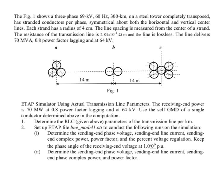
The Fig. 1 shows a three-phase 69-kV, 60 Hz, 300-km, on a steel tower completely transposed,...
Fantastic news! We've Found the answer you've been seeking!
Question:
Expert Answer:
Answer 1 The RLC parameters of the transmission line per km can be calculated using the following equations R 284x102 ohmkm L 2fC Hkm C 2fL Fkm Where ... View the full answer

Related Book For 
Vector Mechanics for Engineers Statics and Dynamics
ISBN: 978-0073212227
8th Edition
Authors: Ferdinand Beer, E. Russell Johnston, Jr., Elliot Eisenberg, William Clausen, David Mazurek, Phillip Cornwell
Posted Date:
