

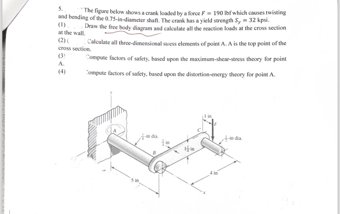
Question: The figure below shows a crank loaded by a force F = 1 9 0 l b f which causes twisting and bending of the
The figure below shows a crank loaded by a force which causes twisting and bending of the indiameter shaft. The crank has a yield strength
Draw the free body diagram and calculate all the reaction loads at the cross section at the wall.
Calculate all threedimensional stress elements of point A A is the top point of the cross section.
Compute factors of safety, based upon the maximumshearstress theory for point
A
Jompute factors of safety, based upon the distortionenergy theory for point A
Step by Step Solution
There are 3 Steps involved in it
1 Expert Approved Answer
Step: 1 Unlock

Question Has Been Solved by an Expert!
Get step-by-step solutions from verified subject matter experts
Step: 2 Unlock
Step: 3 Unlock