

Question: The figure below shows a network where Client PC 1 wishes to establish a connection session with R 2 . The IP and MAC addresses
The figure below shows a network where Client PC wishes to establish a connection session with R The IP and MAC addresses of each device are shown on the figure. Client PC chooses TCP source port number and the destination port number is As shown, there is a network address translation NAT router serving Client PC and PC The NAT router is using a public IP address as shown on the figure andThe figure below shows a network where Client PC wishes to establish a connection session
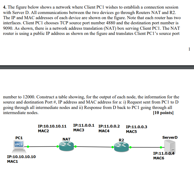
with Server D All communications between the two devices go through Routers NAT and R
The IP and MAC addresses of each device are shown on the figure. Note that each router has two
interfaces. Client PC chooses TCP source port number and the destination port number is
As shown, there is a network address translation NAT box serving Client PC The NAT
router is using a public IP address as shown on the figure and translates Client PCs source port
number to Construct a table showing, for the output of each node, the information for the
source and destination Port # IP address and MAC address for a: i Request sent from PC to D
going through all intermediate nodes and ii Response from D back to PC going through all
intermediate nodes.
points translates Client As source port number to Construct a table showing, for the output of each node, the information for the source and destination Port # IP address and MAC address for a: i Request sent from PC to R going through all intermediate nodes and ii Response from R back to PC going through all intermediate nodes.. pointsThe figure below shows a network where Client PC wishes to establish a connection session with R The IP and MAC addresses of each device are shown on the figure. Client PC chooses TCP source port number and the destination port number is As shown, there is a network address translation NAT router serving Client PC and PC The NAT router is using a public IP address as shown on the figure and translates Client As source port number to Construct a table showing, for the output of each node, the information for the source and destination Port # IP address and MAC address for a: i Request sent from PC to R going through all intermediate nodes and ii Response from R back to PC going through all intermediate nodes.. points
Step by Step Solution
There are 3 Steps involved in it
1 Expert Approved Answer
Step: 1 Unlock

Question Has Been Solved by an Expert!
Get step-by-step solutions from verified subject matter experts
Step: 2 Unlock
Step: 3 Unlock